Multi-mode filter

Inactive Publication Date: 2013-02-28
MESAPLEXX
View PDF4 Cites 39 Cited by
  • Summary
  • Abstract
  • Description
  • Claims
  • Application Information

AI Technical Summary

Benefits of technology

[0013]According to a first aspect of the present invention, there is provided a multi-mode cavity filter, comprising: a dielectric resonator body incorporating a piece of dielectric material, the piece of dielectric material having a shape such that it can support at least a first resonant mode and a second substantially degenerate resonant mode; a conductive layer substantially covering the dielectric resonator body but having one or more apertures therein allowing access

Problems solved by technology

A number of resonators will usually be required to achieve suitable filtering characteristics for commercial applications, resulting in filtering equipment of a relatively large size.
However, the size of single mode filters as described above can make these undesirable for implementation at the top of antenna towers.
However

Method used


Image

  • Multi-mode filter
  • Multi-mode filter
  • Multi-mode filter

Examples


Embodiment Construction

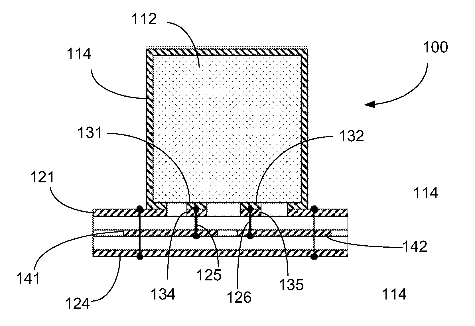
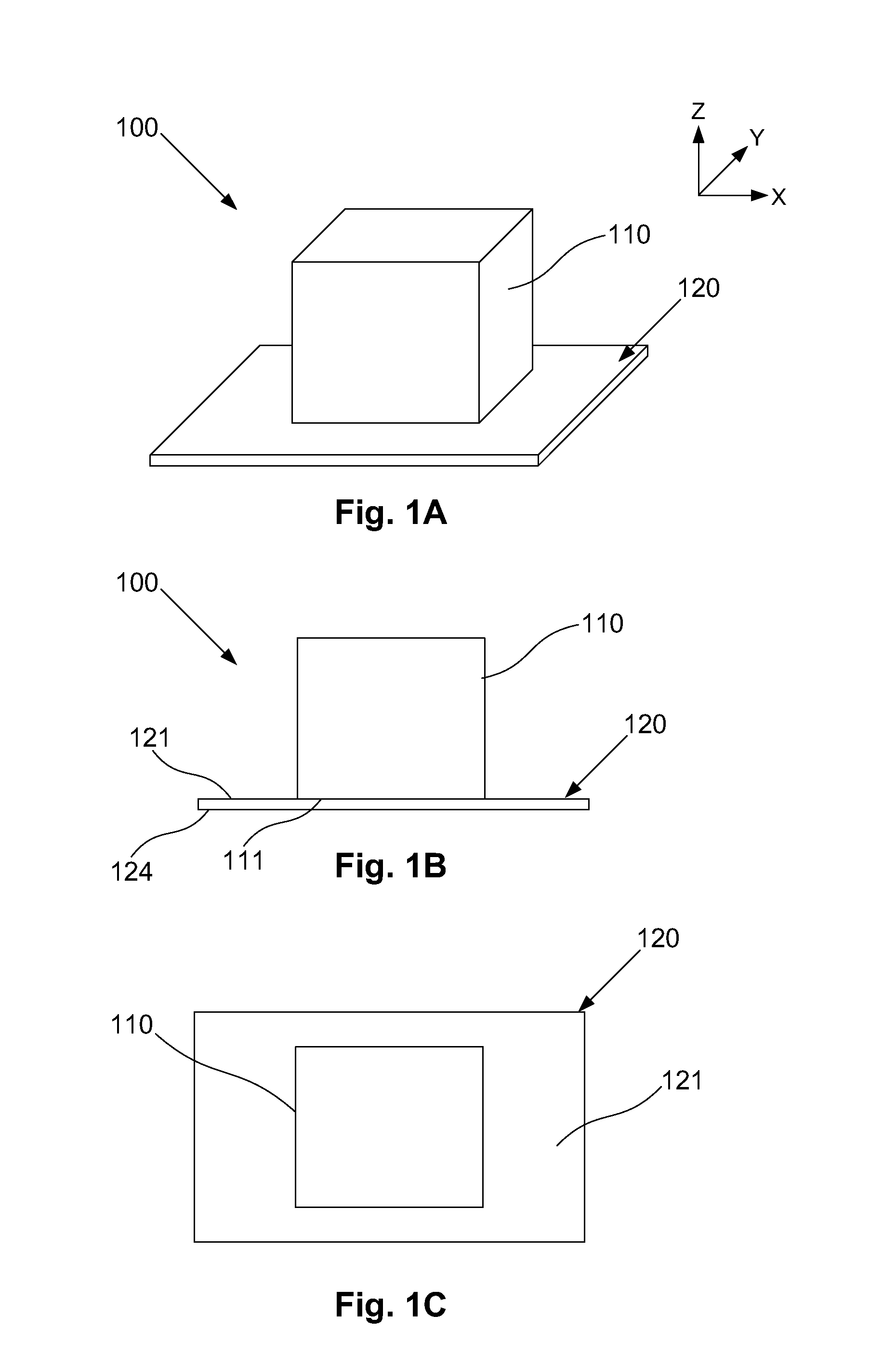
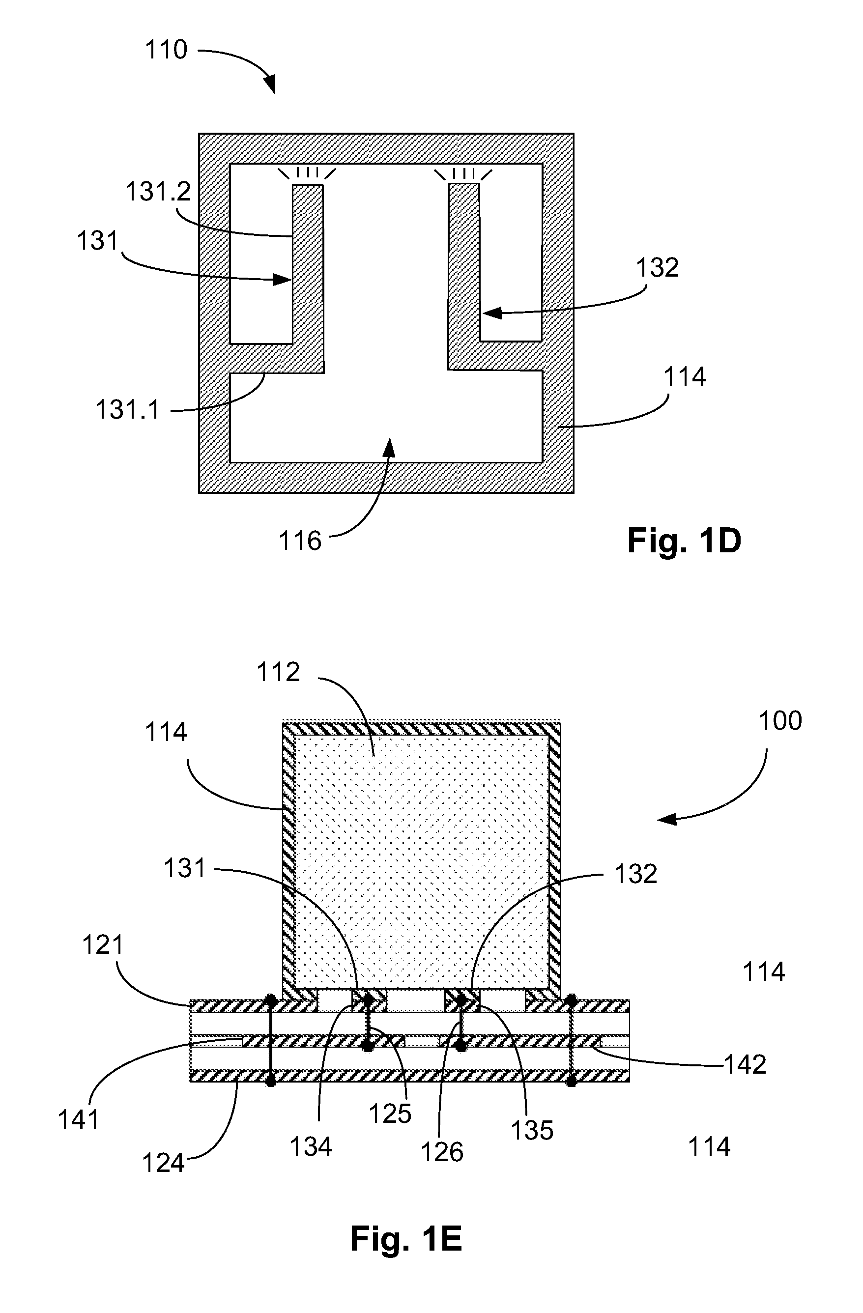
[0022]An example of a multi-mode filter will now be described with reference to FIGS. 1A to 1E.

[0023]In this example, the filter 100 includes a resonator body 110, and a coupling structure 130. The coupling structure 130 comprises at least one coupling path 131, 132, which includes an electrically conductive resonator path extending adjacent to at least part of a surface 111 of the resonator body 110, so that the coupling structure 130 provides coupling to a plurality of the resonance modes of the resonator body.

[0024]In use, a signal can be supplied to or received from the at least one coupling path 131, 132. In a suitable configuration, this allows a signal to be filtered to be supplied to the resonator body 110 for filtering, or can allow a filtered signal to be obtained from the resonator body, as will be described in more detail below.

[0025]The use of electrically conductive coupling paths 131, 132 extending adjacent to the surface 111 allows the signal to be coupled to a plura...


PUM


Abstract

A multi-mode cavity filter, comprising: a dielectric resonator body incorporating a piece of dielectric material, the piece of dielectric material having a shape such that it can support at least a first resonant mode and a second substantially degenerate resonant mode; a conductive layer substantially covering the dielectric resonator body but having one or more apertures therein allowing access to the dielectric resonator body; and a coupling structure arranged in an aperture of the one or more apertures, comprising at least one coupling path for at least one of coupling an input signal to the first and second resonant modes and coupling an output signal from the first and second resonant modes, the coupling path having an open-circuit end located adjacent to an edge of the aperture for controlling a strength of electric field generated by the coupling structure.

Description

CROSS REFERENCE TO RELATED APPLICATIONS[0001]The present application is related to and claims the benefit of Australian Provisional Patent Application No. 2011903389, filed Aug. 23, 2011 and U.S. Provisional Patent Application No. 61 / 531,277, filed Sep. 6, 2011, and is a Continuation-in-Part of both U.S. patent application Ser. No. 13 / 531,169, filed on Jun. 22, 2012, and U.S. patent application Ser. No. 13 / 531,084, filed on Jun. 22, 2012. All four of those disclosures are hereby incorporated by reference in their entirety into the present disclosure.[0002]The present invention relates to filters, and in particular to a multi-mode filter including a resonator body for use, for example, in frequency division duplexers for telecommunication applications.BACKGROUND[0003]The reference in this specification to any prior publication (or information derived from it), or to any matter which is known, is not, and should not be taken as an acknowledgment or admission or any form of suggestion ...

Claims


Application Information

Patent Timeline
IPC IPC(8): H01P1/20
CPCH01P7/105H01P1/2088H01P1/2082
Inventor HENDRY, DAVID ROBERTCOOPER, STEVEN JOHNKENINGTON, PETER BLAKE
Owner MESAPLEXX
Why Eureka
Try Eureka