Autostereoscopic display with a passive cycloidal diffractive waveplate

a technology of diffractive wave plate and autostereoscopic display, which is applied in the direction of color television details, instruments, electrical equipment, etc., can solve the problem of reducing the effective horizontal pixel count viewable for each eye by hal

Active Publication Date: 2013-02-28
REALD SPARK LLC
View PDF1 Cites 26 Cited by
  • Summary
  • Abstract
  • Description
  • Claims
  • Application Information

AI Technical Summary

Benefits of technology

[0007]To overcome the deficiencies of conventional approaches, the present disclosure provides for a new beam deflection approach for displaying images in autostereoscopic format. Conceptually, light from a display is directed into specific viewing regions using a polarization-sensitive beam deflection subsystem, which may comprise, for example, an active liquid crystal (LC) quarter-wave plate modulator and a passive cycloidal grating element (e.g., diffractive waveplate). Such a beam deflection system is then combined with a means for viewing subsets of pixels, based on polarization, from different viewing positions. Some exemplary embodiments comprise an illumination system that both floods an LCD panel and creates a defined eye pupil region, from within which the display is viewable. Deflecting the pupil region between left and right eye positions in synchronization with displayed frame sequential stereo image data creates a desired autostereoscopic 3D sensation. Other embodiments may employ a similar polarization-sensitive beam deflection subsystem in conjunction with a means of viewing subsets of pixels from different viewing positions, such as a parallax barrier or lenslet array, allowing freedom of head movement while maintaining stereo viewing. Additional embodiments would utilize an emissive display technology such as OLED (Organic Light Emitting Device) in combination with active polarization control and a polarization beam deflection subsystem.

Problems solved by technology

A disadvantage of the technology is that the viewer generally has to be positioned in a well-defined location to experience the 3D effect.
Another disadvantage to parallax-barrier type displays is that the effective horizontal pixel count viewable for each eye is reduced by one-half.
Unfortunately, both the parallax barrier and lenticular lens array technologies have fabrication procedures that demand precision alignment of the optic to the TFT and color filter planes.

Method used


Image

  • Autostereoscopic display with a passive cycloidal diffractive waveplate
  • Autostereoscopic display with a passive cycloidal diffractive waveplate
  • Autostereoscopic display with a passive cycloidal diffractive waveplate

Examples


Embodiment Construction

[0030]A static (i.e., passive) cycloidal diffractive waveplate (CDW) is an optical component which may be approximately a micron-thick with diffraction efficiency as high as a Bragg grating (˜100%), but with a spectrum of wavelengths and divergence angles that are two to three orders broader. Typical CDW devices are fabricated utilizing photo-alignment layers that are exposed to two coherently orthogonal circular polarized beams generating a specific intensity pattern, which is imprinted into the alignment layer, and which then has a layer of reactive mesogen (polymerizable liquid crystal material) material spin coated on and fixated with standard processing.

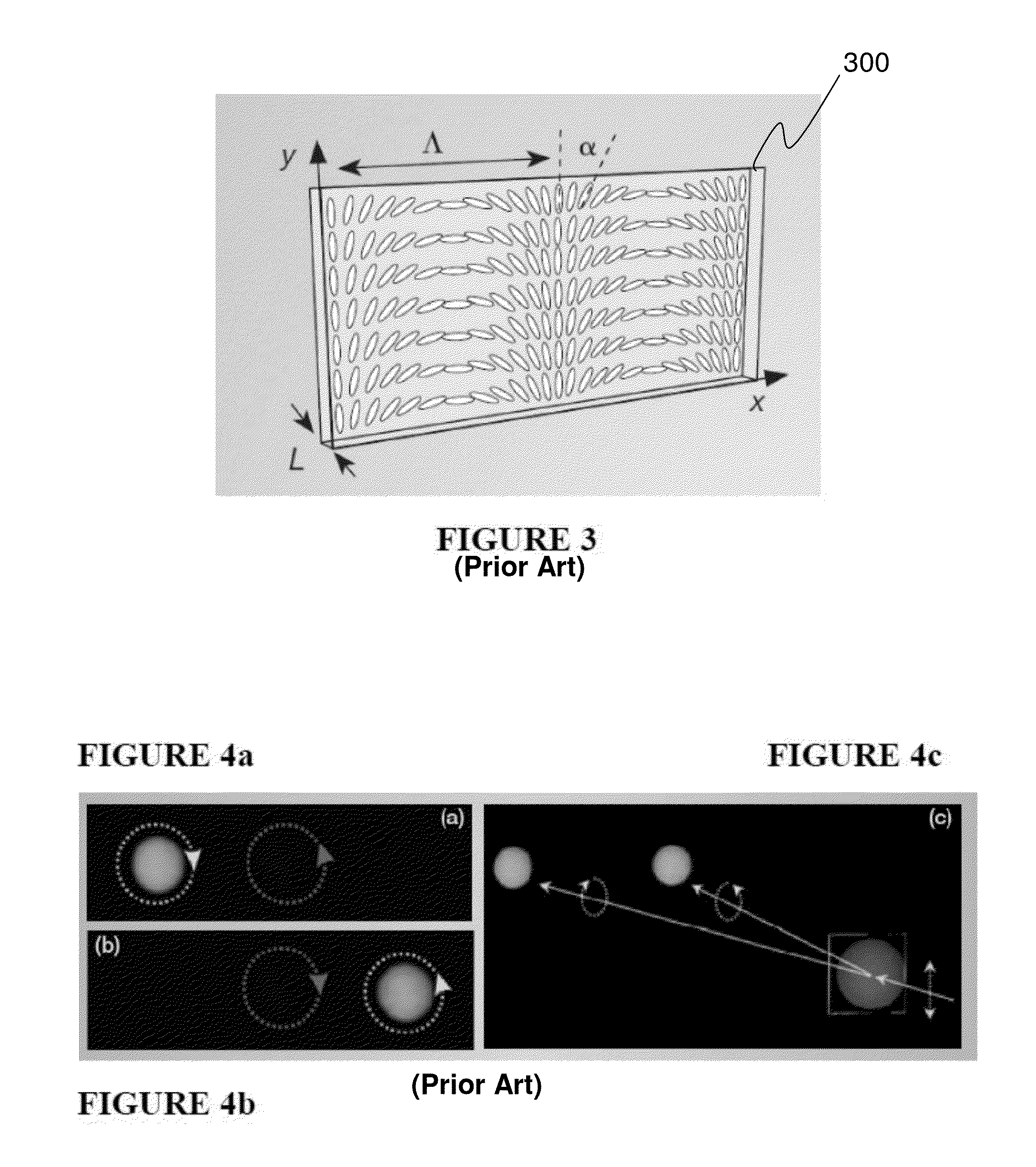
[0031]FIG. 3 is a schematic diagram illustrating liquid crystal optical axis orientation of a cycloidal diffractive waveplate 300, with L being film thickness, α and Λ being functions of exposure wavelength and incident angles. FIG. 3 illustrates a conventional cycloidal diffractive waveplate 300 and the optical axis orientation...


PUM


Abstract

A new beam deflection approach is provided for displaying images in autostereoscopic format. Conceptually, polarized light from a display is directed into specific viewing regions using a polarization-sensitive beam deflection sub-system that comprises, in exemplary embodiments, an active liquid crystal quarter-wave plate modulator and a passive cycloidal grating element, such as a diffractive waveplate. Specific embodiments may comprise an illumination system that both floods an LCD panel and creates a defined eye pupil region, from within which the display is viewable. Deflecting the pupil region between left and right eye positions in synchronization with displayed frame sequential stereo image data creates desirable autostereoscopic 3D viewing. Other embodiments employ a similar beam deflection sub-system in conjunction with a means of viewing subsets of pixels from different viewing positions, such as a parallax barrier or lenslet array, allowing freedom of head movement while maintaining stereo viewing.

Description

CROSS-REFERENCE TO RELATED APPLICATIONS[0001]The present application claims priority to U.S. Provisional Pat. App. Ser. No. 61 / 526,756, filed Aug. 24, 2011, and entitled “Auto-stereoscopic display with a passive cycloidal diffractive waveplate.”TECHNICAL FIELD[0002]Generally, this disclosure relates to autostereoscopic displays, and more specifically relates to beam deflection approaches for displaying images in autostereoscopic displays.BACKGROUND[0003]A spatially multiplexed autostereoscopic display system typically has either a lenticular screen or a parallax barrier. The concept of lenticular screens and parallax barrier type approaches to spatially multiplexed autostereoscopic images are over 100 years old. Each of these approaches allows for each eye to only see a portion of the image, which is particular to either the left or right eye frame sequential stereo image data.[0004]FIG. 1 is a schematic diagram 100 showing an example of a parallax-barrier type display. A parallax b...

Claims


Application Information

Patent Timeline
Patent Type & Authority Applications(United States)
IPC IPC(8): H04N13/04G02B30/25
CPCH04N13/0404G09G3/003H04N13/0468H04N13/0406H04N13/305H04N13/307H04N13/366
Inventor RAMSEY, ROBERT A.ROBINSON, MICHAEL G.
Owner REALD SPARK LLC
Why Eureka
Try Eureka