
Switching power supply

Inactive Publication Date: 2013-02-28
SAMSUNG ELECTRO MECHANICS CO LTD
View PDF0 Cites 10 Cited by
  • Summary
  • Abstract
  • Description
  • Claims
  • Application Information

AI Technical Summary

Benefits of technology

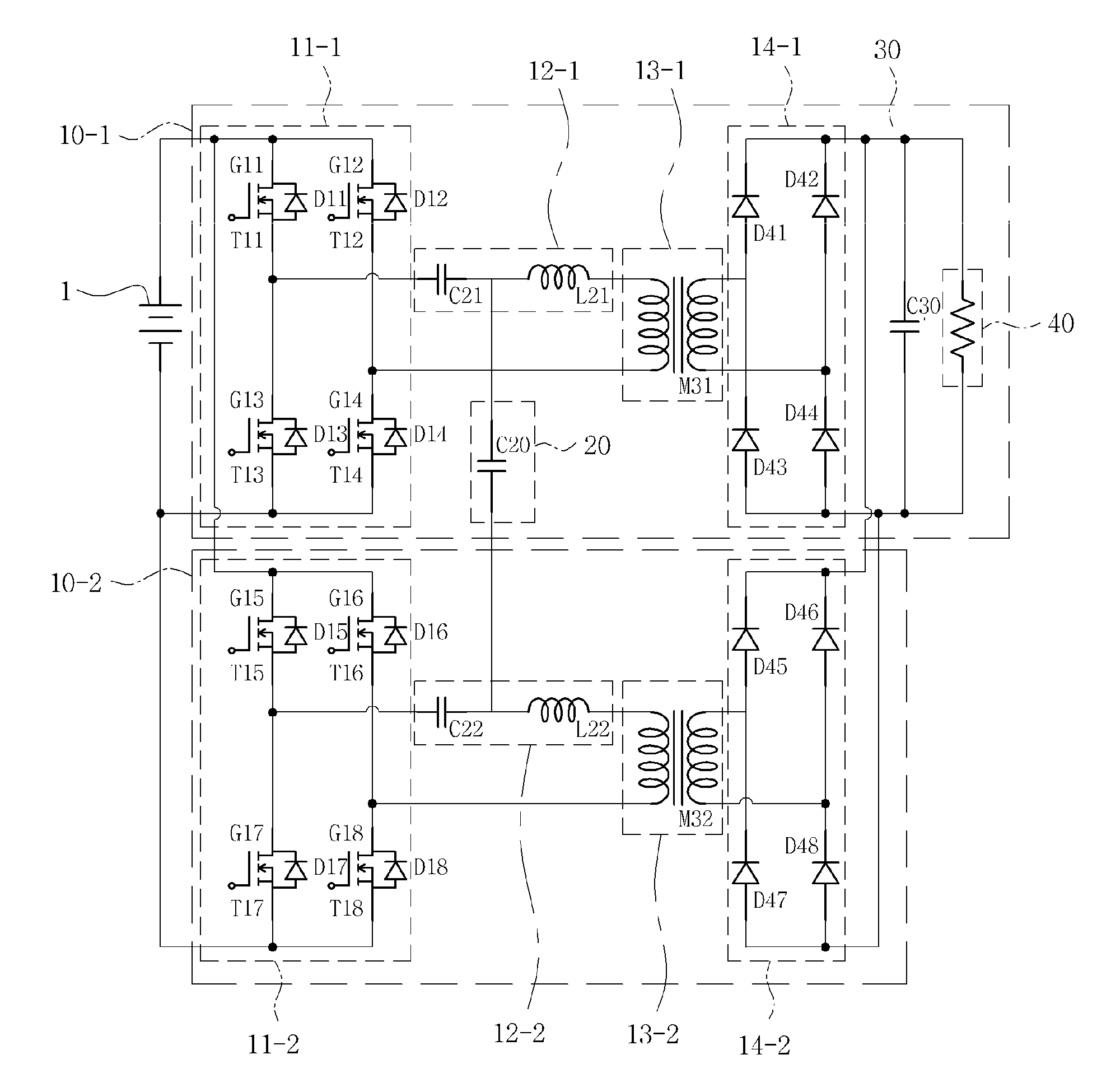
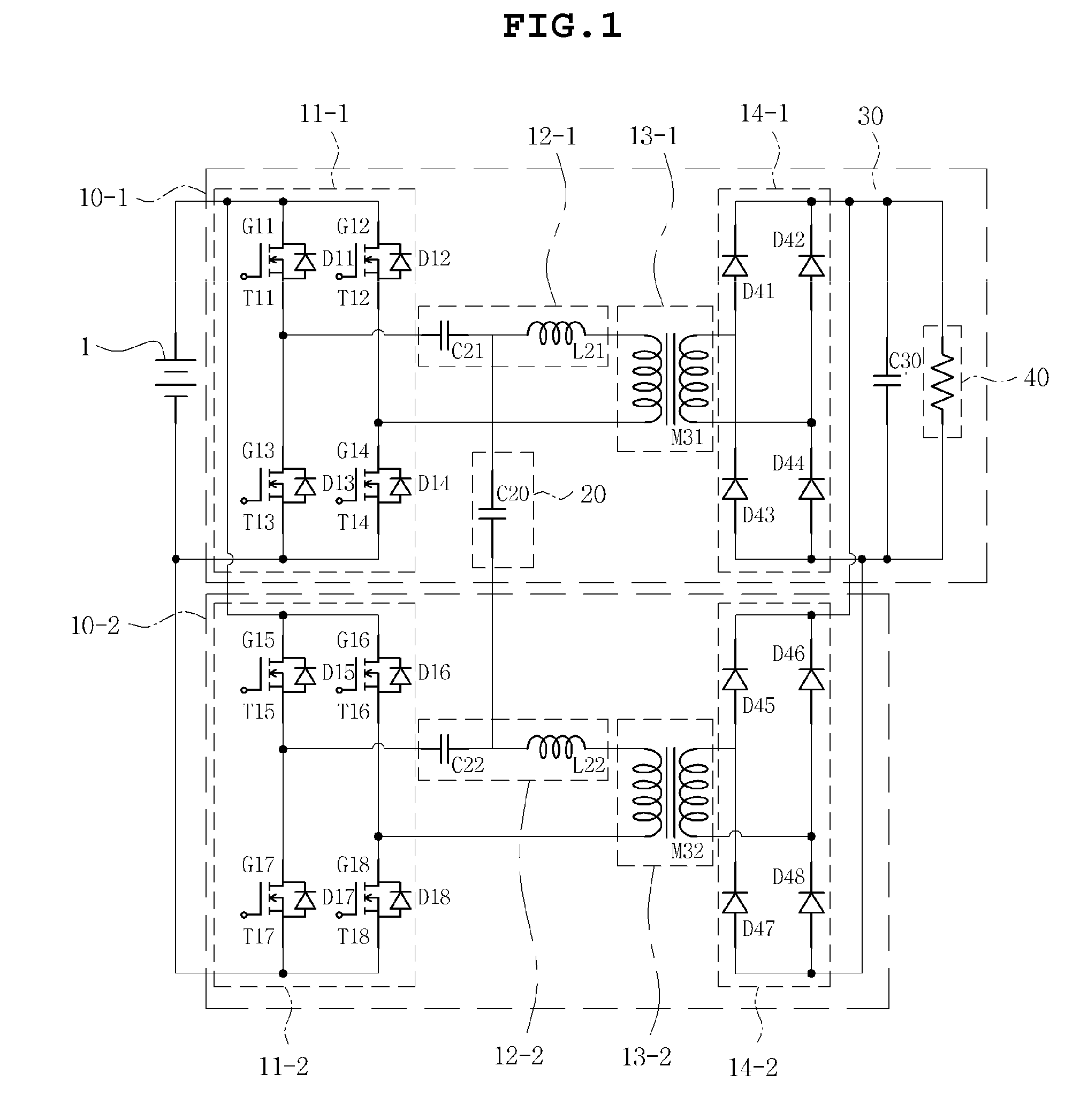
This patent is about a new type of switching power supply that prevents a problem called "current concentration" which can happen when using resonant circuits. This new power supply has a balance circuit that is added to connect two or more resonant circuits together. This balance circuit helps to even out the current in the resonant circuits, which can make them more efficient and reliable. The power supply also includes a DC-AC converter, an AC-DC converter, and a contactless transformer to convert and boost the power. Overall, this patent describes a way to create a more stable and reliable switching power supply that can handle higher power levels.

Problems solved by technology

In this situation, since the switching power supply converts a DC power into an alternate current (AC) power by switching the DC power and then performs rectification and planarization to obtain an output power, the increase in output power causes an increase in noise.
However, when the current resonant circuits are connected in parallel with each other in the power supply using the current resonant circuits, a current is concentrated in any resonant circuit due to deviation between circuit parameters.
Therefore, a process is complicated, such that implementation is not easy.
However, in this patent, frequencies operating each resonant circuit are changed, such that an unusual ripple voltage is generated in an output.

Method used


Image

  • Switching power supply
  • Switching power supply
  • Switching power supply

Examples


Embodiment Construction

[0036]The terms and words used in the present specification and claims should not be interpreted as being limited to typical meanings or dictionary definitions, but should be interpreted as having meanings and concepts relevant to the technical scope of the present invention based on the rule according to which an inventor can appropriately define the concept of the term to describe most appropriately the best method he or she knows for carrying out the invention.

[0037]The above and other objects, features and advantages of the present invention will be more clearly understood from the following detailed description taken in conjunction with the accompanying drawings. In the specification, in adding reference numerals to components throughout the drawings, it is to be noted that like reference numerals designate like components even though components are shown in different drawings. Further, when it is determined that the detailed description of the known art related to the present ...


PUM


Abstract

Disclosed herein is a switching power supply including: N sub switching power supplying unit each converting a direct current (DC) power supplied from a power source into an alternate current (AC) power, boosting or bucking the AC power using a resonant circuit and a contactless transformer, converting the boosted or bucked AC power into a DC power, and outputting the converted DC power; and a balance circuit connecting between the resonant circuits of the N sub switching power supplying units to thereby allow currents to be balanced between the resonant circuits.

Description

CROSS REFERENCE TO RELATED APPLICATION[0001]This application claims the benefit of Korean Patent Application No. 10-2011-0085318, filed on Aug. 25, 2011, entitled “Switched Power Supply”, which is hereby incorporated by reference in its entirety into this application.BACKGROUND OF THE INVENTION[0002]1. Technical Field[0003]The present invention relates to a switching power supply.[0004]2. Description of the Related Art[0005]In recent years, in accordance with the development of a switching element capable of withstanding a relatively large high frequency current and voltage, a switching mode power supply has been mainly used as a power supply obtaining a desired direct current (DC) voltage by rectifying commercial power.[0006]The switching mode power supply, which has a high switching frequency, allows a transformer and other device to have a small size, is a high power DC-DC converter, and is used as a power supply for various electronic devices.[0007]Meanwhile, in accordance with ...

Claims


Application Information

Patent Timeline
IPC IPC(8): H02M3/335
CPCH02M3/285H02M3/01H02M3/33573Y02B70/10
Inventor LEE, BU WONCHO, WON JINHAN, KYU BUM
Owner SAMSUNG ELECTRO MECHANICS CO LTD
Learn More