Ball turret heat sink and EMI shielding

a technology of electromagnetic shielding and ball turret, applied in the direction of instruments, cameras, transportation and packaging, etc., can solve the problems of limited power for such small drones, affecting the safety of users, so as to maximize the amount of interior surface, prevent exposure to the elements, and enhance thermal conductivity

Active Publication Date: 2013-02-28
AEROVIRONMENT INC
View PDF4 Cites 48 Cited by
  • Summary
  • Abstract
  • Description
  • Claims
  • Application Information

AI Technical Summary

Benefits of technology

[0011]Joining the front and rear shells may be an electrically- and thermally-conductive elastomeric o-ring situated in the o-ring groove and in contact with the conductive surface of both the front and rear shells. In some configurations, the conductive coating of the inner surface of the shell may wrap around and cover an outer part of the shell to maintain electrical contact between the o-ring groove and the internal surface of the shell. Any such exterior coating of metal is preferably covered by a portion of the other shell, so as to prevent exposure to the elements.
[0012]The o-ring may seal the connection between the front and rear shells so that the enclosure formed by the shells is water-resistant or waterproof under the design conditions of the aircraft with at least a margin or safety. Preferably, the o-ring may be electrically conductive and have enhanced thermal conductivity beyond typical elastomeric substances. For example, specialized elastomeric substances known in the art might have thermal conductivities at normal operating conditions greater than about 0.50 W / (m·K), or often significantly higher. Electrically, there is preferably an electrical connection between the interior front and rear shell surfaces through the o-ring so that as a whole, the turret acts as an electromagnetic shield. Thus, it is preferable to maximize the amount of interior surface that is electrically conductive, and to maintain electrical connection throughout the interior surface.

Problems solved by technology

Although many presently used drones are roughly the same scale size as piloted aircraft, such aircraft are both relatively expensive and may be detected due to their size.
Smaller drones have certain tradeoffs as they cannot carry the amount of payload of a larger drone.
Further, power for such smaller drones is limited due to the size of the aircraft and therefore operating periods are also limited.
Polymer and glass shells have the disadvantage that they may allow electromagnetic radiation to enter the turret and interfere with the sensitive camera equipment.
Polymers and glasses are also generally thermal insulators, so that heat may build up inside the turret, compromising the equipment.
Solid metallic turret shells are possible, but are heavy and not ideal for aerial reconnaissance craft.

Method used


Image

  • Ball turret heat sink and EMI shielding
  • Ball turret heat sink and EMI shielding
  • Ball turret heat sink and EMI shielding

Examples


Embodiment Construction

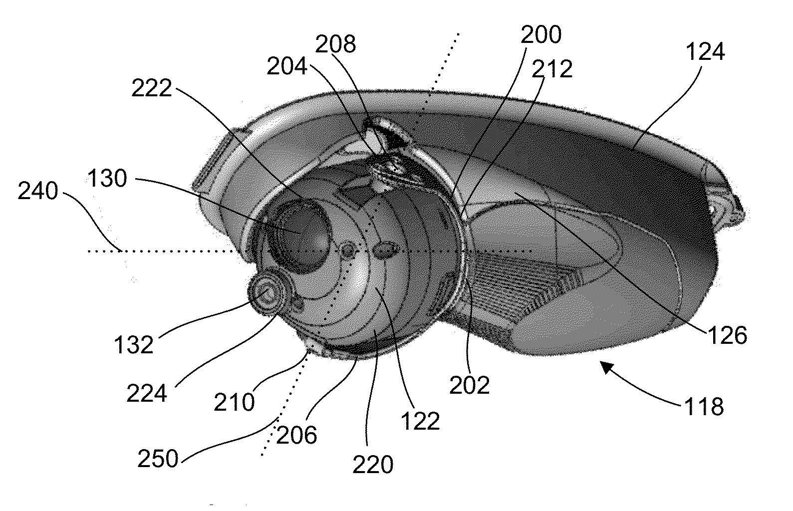
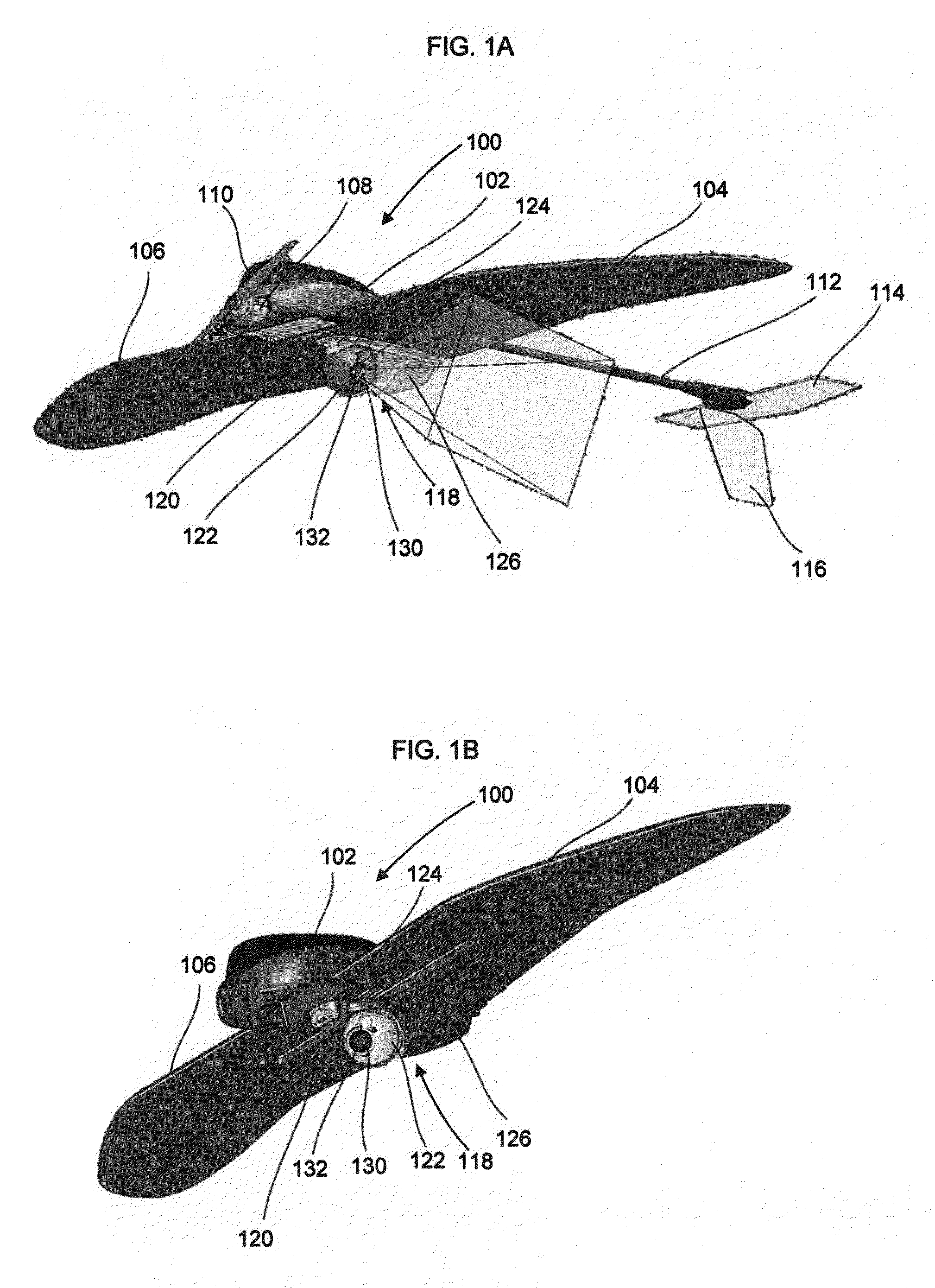
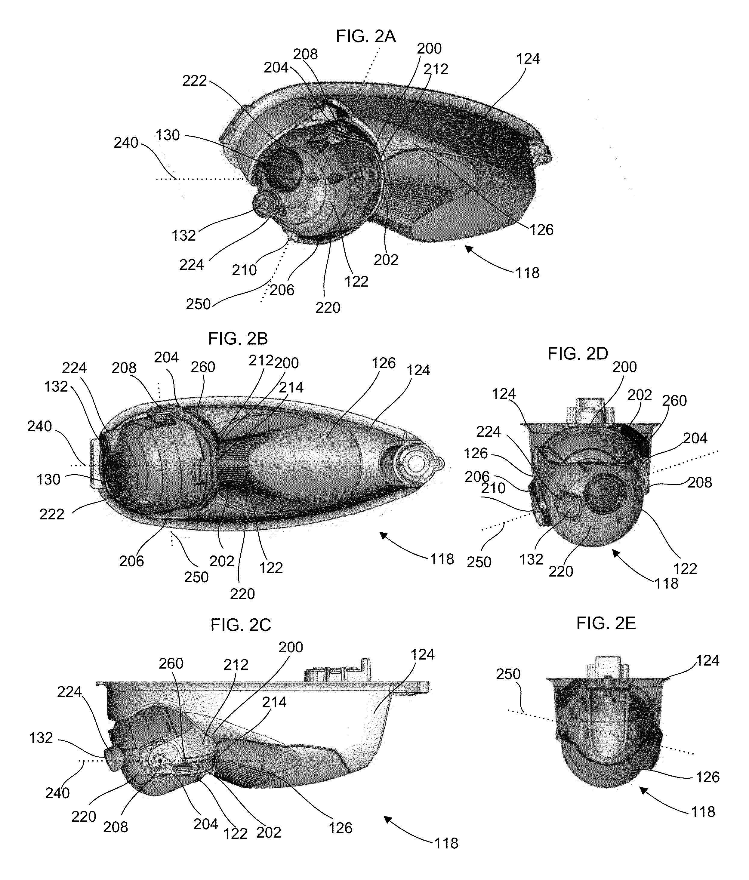
[0024]Various example embodiments of the present inventions are described herein in the context of providing a shell for a camera turret for attachment to a reconnaissance aircraft that may shield against electromagnetic radiation and may effectively dissipate heat that builds up in the system. The shell is also preferably lightweight and waterproof.

[0025]Those of ordinary skill in the art will understand that the following detailed description is illustrative only and is not intended to be in any way limiting. Other embodiments of the present inventions will readily suggest themselves to such skilled persons having the benefit of this disclosure, in light of what is known in the relevant arts, the provision and operation of information systems for such use, and other related areas.

[0026]Not all of the routine features of the exemplary implementations described herein are shown and described. In the development of any such actual implementation, numerous implementation-specific deci...


PUM


Abstract

A water resistant and electromagnetically shielded turret assembly, suitable for attachment to the undersurface of an unmanned surveillance aircraft. The turret, in its several variations, may contain one or more cameras, and may contain an internal positioning motor, which can be easily accessible for servicing.

Description

CROSS-REFERENCE TO RELATED APPLICATION[0001]This application is related to U.S. patent application Ser. No. _______, (attorney docket number 435410-000071) entitled “Tilt-Ball Turret with Gimbal Lock Avoidance,” by Tom Szarek et al., filed currently herewith, the entire disclosure of which is hereby incorporated by reference.TECHNICAL FIELD[0002]This subject matter relates generally to heat transfer and electromagnetic shielding with application to a ball turret.BACKGROUND[0003]The way that the Vietnam War is now remembered as the helicopter war, the current conflicts in Iraq and Afghanistan may be remembered for the use of unpiloted aerial surveillance (UAV) craft or drones. Drones may facilitate remote intelligence gathering, alleviating the need for foot soldiers to enter into hostile areas “blind,” with little or no information about the location and strength of hostile forces. Drones may provide close combat support, such as identifying and eliminating targets of interest, alle...

Claims


Application Information

Patent Timeline
Patent Type & Authority Applications(United States)
IPC IPC(8): G03B17/00
CPCB64D47/08G03B15/006B64C2201/127G03B37/02G03B17/08B64U2101/30
Inventor DIMOTAKIS, MANOLIS PAVLOS
Owner AEROVIRONMENT INC
Why Eureka
Try Eureka