Fan modules and server equipment
- Summary
- Abstract
- Description
- Claims
- Application Information
AI Technical Summary
Benefits of technology
Problems solved by technology
Method used
Image

Examples
first embodiment
[0046]A first embodiment is described with reference to FIGS. 4, 5 and 6. FIG. 4 is an explanatory view showing a state of airflow entering the axial flow fan exposed to the atmosphere. FIG. 5 is an explanatory view showing a state of airflow entering the axial flow fan mounted in an information instrument. FIG. 6 is a graph showing a comparison in velocity distribution of airflow entering the axial flow fan between when the axial flow fan is exposed to the atmosphere and when it is mounted in the information instrument.
[0047]In cooling a variety of information instruments, resistor bodies such as boards which disturb airflow are generally located on the upstream side of a cooling fan. If the airflow thus disturbed by these resistor bodies enters the cooling fan mounted in an information instrument, noises are generated. As shown in FIG. 4, general-purpose small-sized axial flow fans are presupposed to be used under atmosphere-exposure conditions; therefore, they are designed under ...
second embodiment
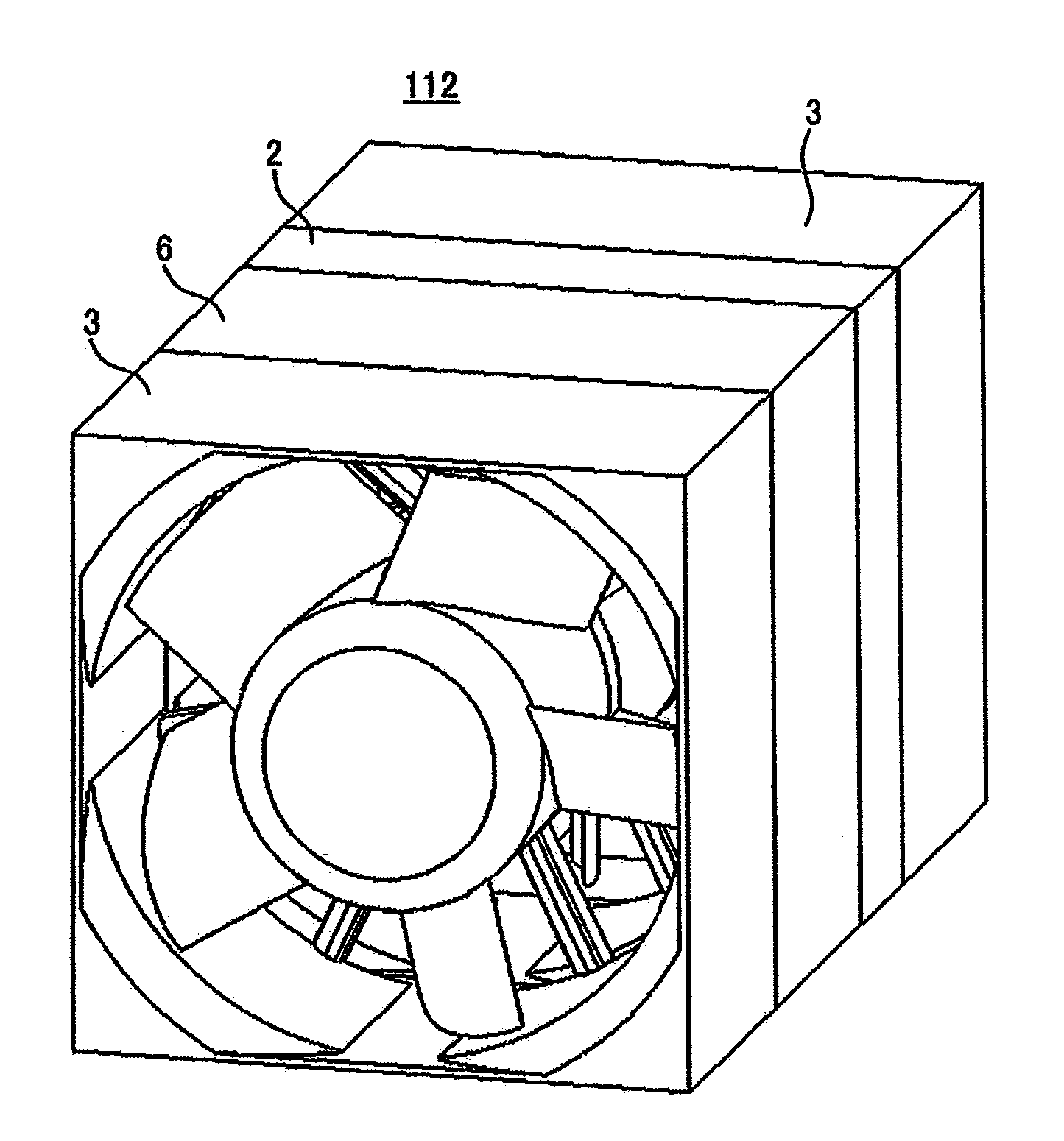
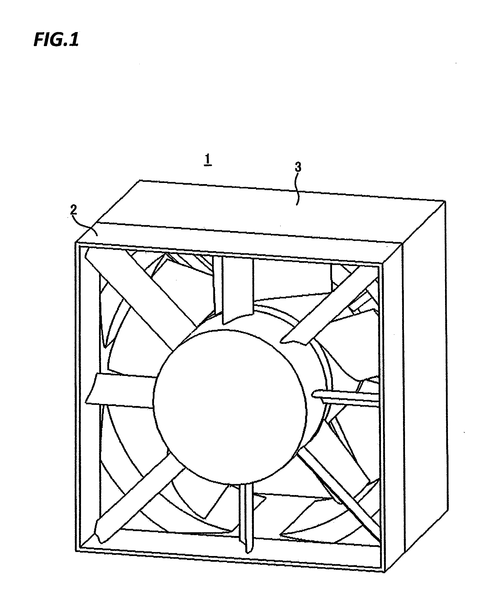
[0050]As shown in FIG. 1, the fan module 1 has the stator 2 disposed immediately in front of the axial flow fan 3. The rotor vanes 32 are rotated along with the rotation of the boss 31 to which the motor of the axial flow fan 3 is attached. The rotation of the rotor vanes 32 causes interference with the stator vanes 22 of the stator. Thus, there is concern about increased noise of frequencies resulting from the number of the rotor vanes 32 or of the stator vanes 22.
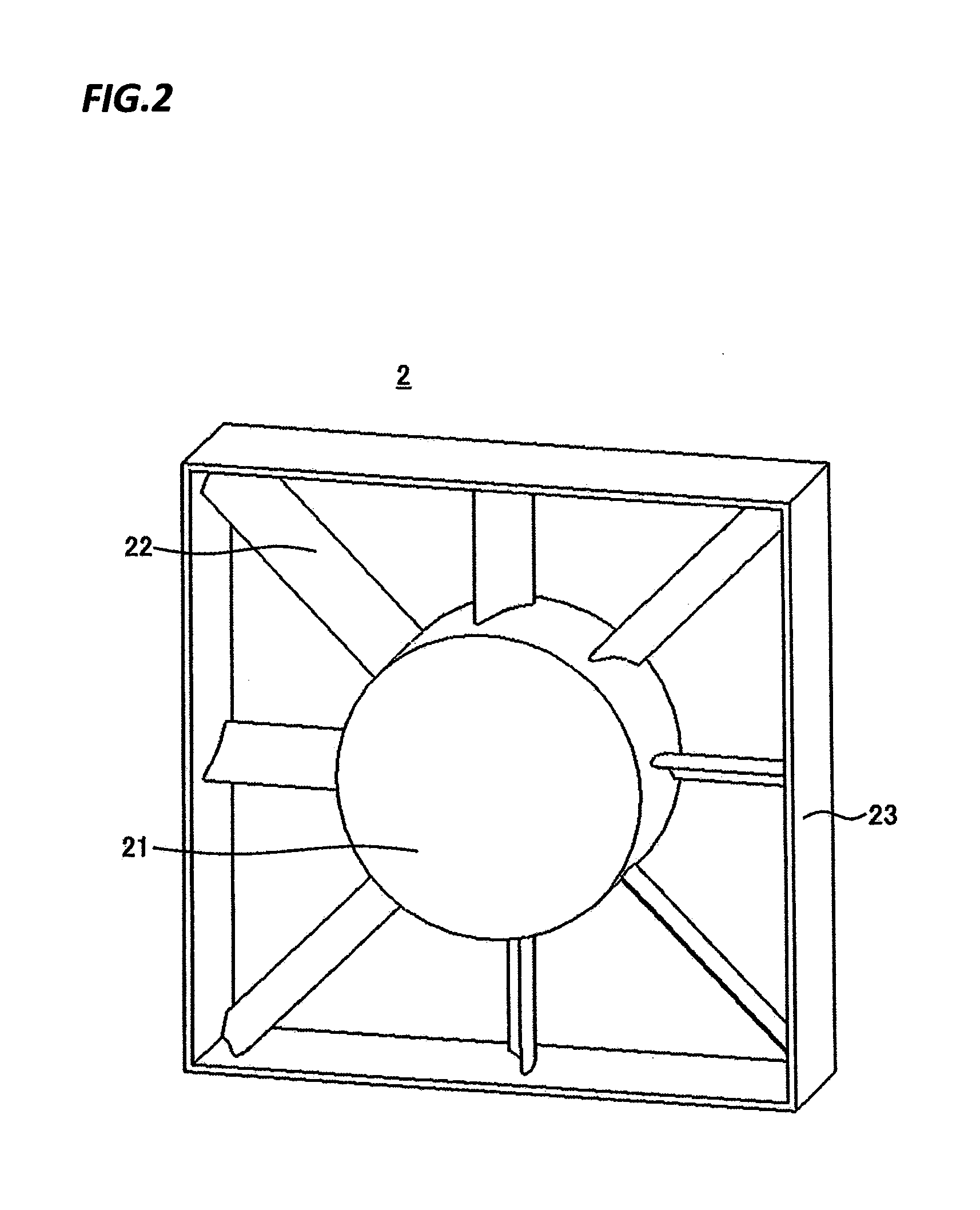
[0051]To address the concern noise, a second embodiment focuses on a positional relationship between the stator vanes 22 and the rotor vanes 32. This suppresses increase in the noise of frequencies resulting from the number of the rotor vanes 32 or the stator vanes 22.
[0052]FIG. 7 partially shows the fan module 1 as viewed from the upstream side of airflow in the rotational-axial direction of the rotor vanes 32. As described earlier, the interference between the rotor vanes 32 and the stator vanes 22 occurs when the rotor...
third embodiment
[0057]In a third embodiment, a configuration in which the direction of airflow is changed by stator vanes is added to that of the first or second embodiment to thereby increase the amount of airflow in a fan module mounted in server equipment such as an information instrument. FIG. 9 is a schematic cross-sectional view of a fan module of the third embodiment, showing a positional relationship between a stator vane 22 and a rotor vane 32. The stator vane 22 of a stator and the rotor vane 32 of an axial flow fan are arranged from the upstream side of airflow. The rotor vane 32 is rotated in a rotational direction R. The stator vane 22 is warped in a U-shape in cross-section relative to the rotational direction R.
[0058]A velocity component 51 of airflow entering the fan module is changed in direction by the stator vane 22 and turned to a velocity component 52 of the airflow, which enters the rotor vane 32. In other words, because of the presence of the stator vane 22, the airflow havin...
PUM
 Abstract
Description
Claims
Application Information
PatSnap Eureka turns technology decisions into work you can execute. Powered by our Innovation Knowledge Graph, it runs expert workflows across engineering, life sciences, materials and intellectual property. Get your review-ready output in minutes.


