Interbody fusion implant and screw guide

a technology of interbody fusion and screw guide, which is applied in the field of implantable medical devices, can solve the problems of inability to easily access upwardly angled bone screw supporting bores in the cage, and inherent difficulty in placing screws between the cage and a higher vertebra in the spin

Inactive Publication Date: 2013-02-28
TALWAR VIKRAM
View PDF9 Cites 26 Cited by
  • Summary
  • Abstract
  • Description
  • Claims
  • Application Information

AI Technical Summary

Benefits of technology

[0005]With this invention, an improved spinal fusion cage implant and associated screw guide tool and screw orientation, as well as a unique hybrid screw are provided. Whereas the classic design of ALIF implants has been to go through the implant first and then into the end plate and vertebral body, with this type of cage and screw techniqu

Problems solved by technology

There is some inherent difficulty in placing screws between the cage and a higher vertebra in the spine to fix the cage in place, particularly when fusing L5 and S1, and when the L5-S1 disk

Method used


Image

  • Interbody fusion implant and screw guide
  • Interbody fusion implant and screw guide
  • Interbody fusion implant and screw guide

Examples


Embodiment Construction

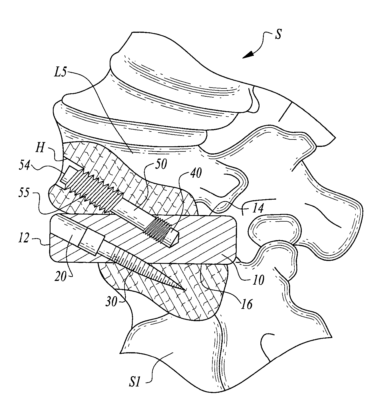
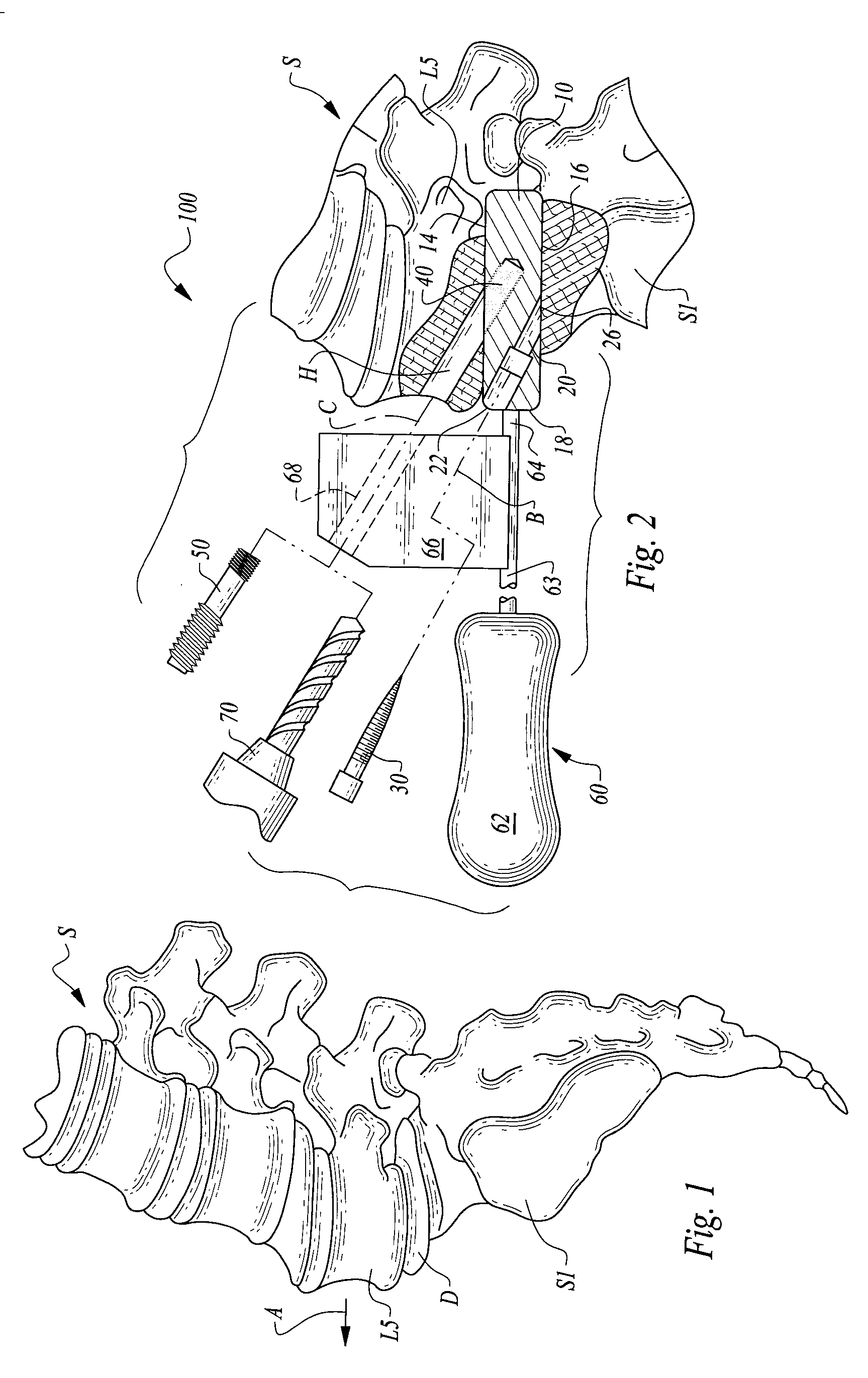
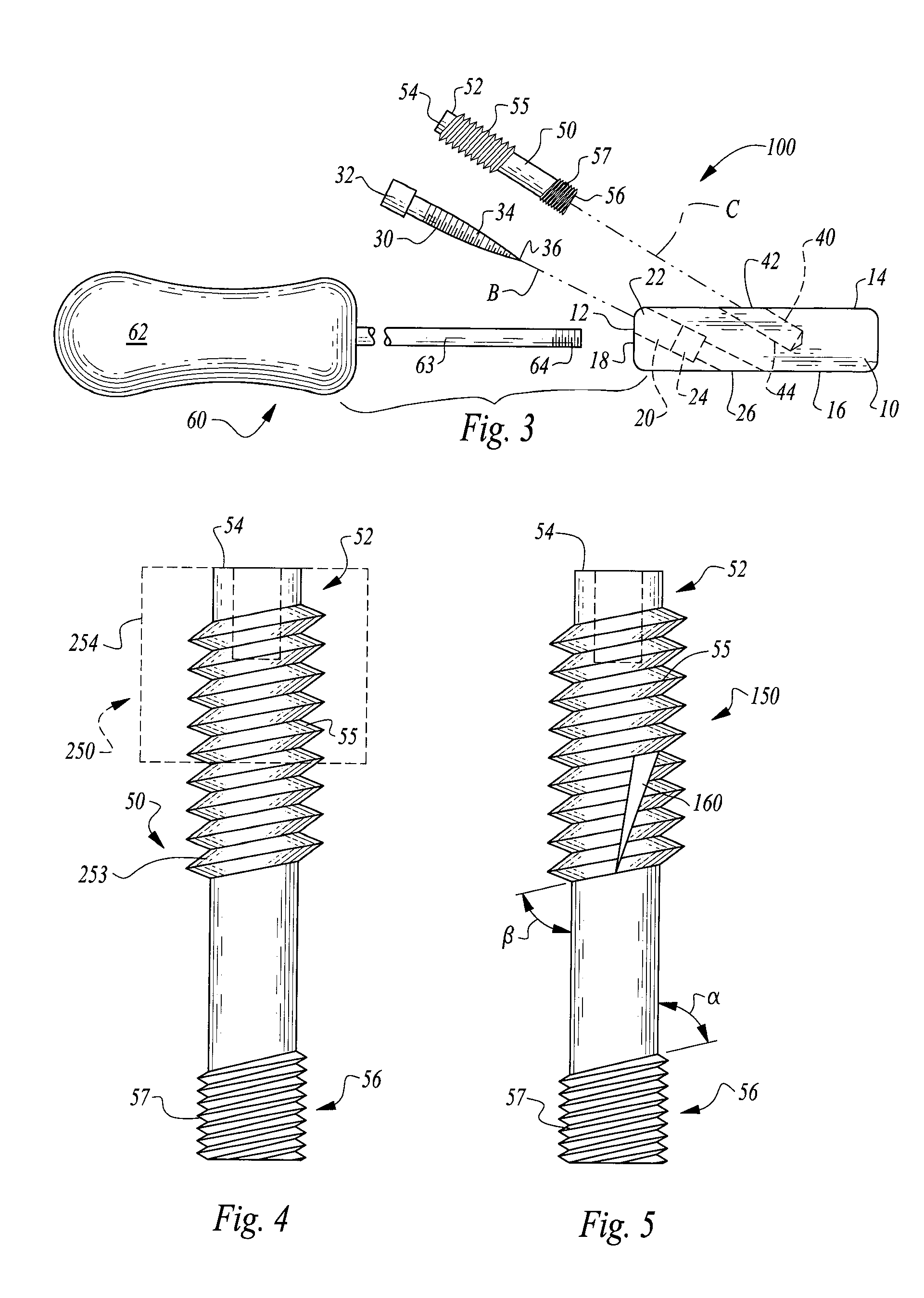
[0026]Referring to the drawings, wherein like reference numerals represent like parts throughout the various drawing figures, reference numeral 10 is directed to a cage implant for use in a vertebral interbody fusion procedure (FIGS. 2 and 7), according to a preferred embodiment of this invention. The implant 10 is utilized as part of a system 100 which includes a guide tool 60, drill 70 or other hole forming tool and bone screws 30 and hybrid screws 50 for securing of the implant 10 to adjacent structures such as the L5 vertebra and the S1 sacrum adjacent the implant, when used at the L5 / S1 joint. Following the system 100 of this invention, the implant 10 is mechanically secured to both cephalid and caudal adjacent structures for secure fixation of the implant 10 during fusion of the adjacent vertebral structures together. While depicted primarily for interbody vertebral fusion, and especially fusion of portions of the lumbar spine S, and in particular the L5 / S1 joint, the implant ...


PUM


Abstract

An interbody fusion implant fits between adjacent vertebrae for fixation during fusion thereof. Upper bores extend into a cephalid surface of the implant and preferably include threads therein. A guide tool is removably attachable to the implant which supports guide bores along centerlines aligned with the upper bores in the implant. A drill can pass along these guide bores to form holes in a vertebra adjacent the cephalid surface of the implant which is precisely aligned with the upper bores. A hybrid screw then passes through these holes in the vertebra adjacent the cephalid surface and threads into the upper bores to secure the implant to the adjacent cephalid vertebra. Bone screws can also be used to secure the implant to caudal vertebra by passing through bores passing through the implant, such that the implant is securely mechanically fastened to both cephalid and caudal vertebrae adjacent the implant.

Description

CROSS-REFERENCE TO RELATED APPLICATIONS[0001]This application claims benefit under Title 35, United States Code §119(e) of U.S. Provisional Application No. 61 / 575,639 filed on Aug. 25, 2011.FIELD OF THE INVENTION[0002]The following invention relates to implantable medical devices such as those used for interbody fusion between adjacent vertebrae, and especially between lumbar vertebrae and the sacrum. More particularly, this invention relates to interbody fusion implant cages which accommodate screws for attachment of the implant to vertebrae on both cephalid and caudal sides of the implant.BACKGROUND OF THE INVENTION[0003]Anterior lumbar interbody fusion (ALIF) has become an increasingly useful approach for fusing the lumbar spine. With ALIF procedures, a disk between adjacent vertebrae is removed and a fusion cage implant is inserted into the disk space. Through known techniques, bone growth through and around the cage is promoted to fuse the adjacent vertebrae together. In one AL...

Claims


Application Information

Patent Timeline
IPC IPC(8): A61F2/44
CPCA61F2/442A61F2/4455A61F2/4611A61F2002/3056A61F2002/30672A61F2002/30774A61F2002/4687A61F2002/30787A61B17/1671A61B17/1757A61B17/7055A61B17/863A61F2002/30785A61F2002/30558A61F2/30771
Inventor TALWAR, VIKRAM
Owner TALWAR VIKRAM
Why Eureka
Try Eureka