Method of calibrating gear measuring device

Active Publication Date: 2013-02-28
MITSUBISHI HEAVY IND MACHINE TOOL CO LTD
View PDF1 Cites 16 Cited by
  • Summary
  • Abstract
  • Description
  • Claims
  • Application Information

AI Technical Summary

Benefits of technology

[0047]According to the present invention, the position of the gauge head can be calibrated by arithmetic processing according to the difference between the tooth profile gradient errors of the tooth profile measurement obtained in the two steps, and, when the same tooth is measured in the two steps, the cause of the tooth profile errors can b

Problems solved by technology

If a workpiece gear to be processed is large, a defective product is not allowed to be produced.
However, if thermal deformation occurs in the gear measuring device including the measuring instrument due to the surrounding temperature or heat, etc. generated upon processing of the workpiece gear, even when the gauge head is p

Method used


Image

  • Method of calibrating gear measuring device
  • Method of calibrating gear measuring device
  • Method of calibrating gear measuring device

Examples


Example

EXAMPLE

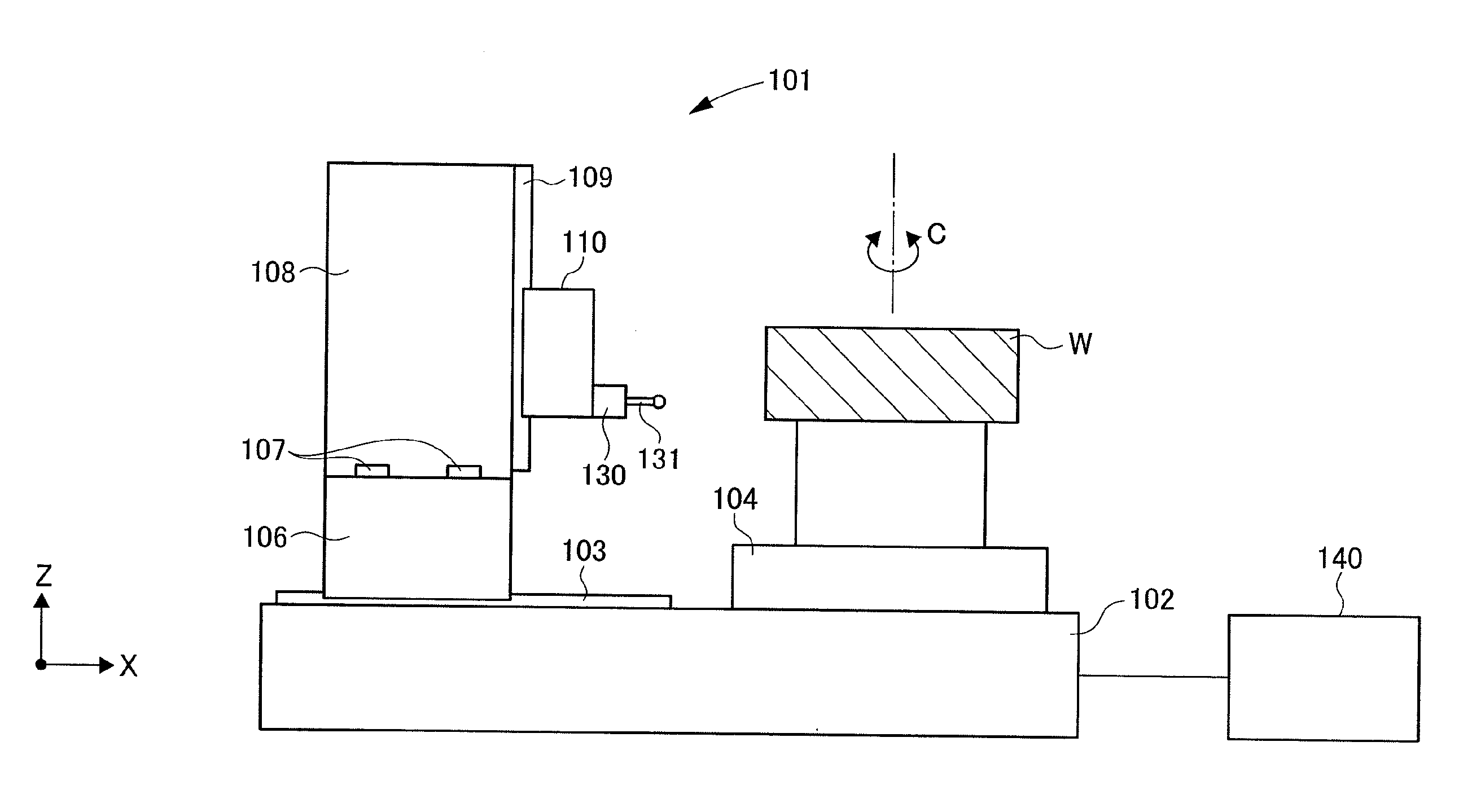
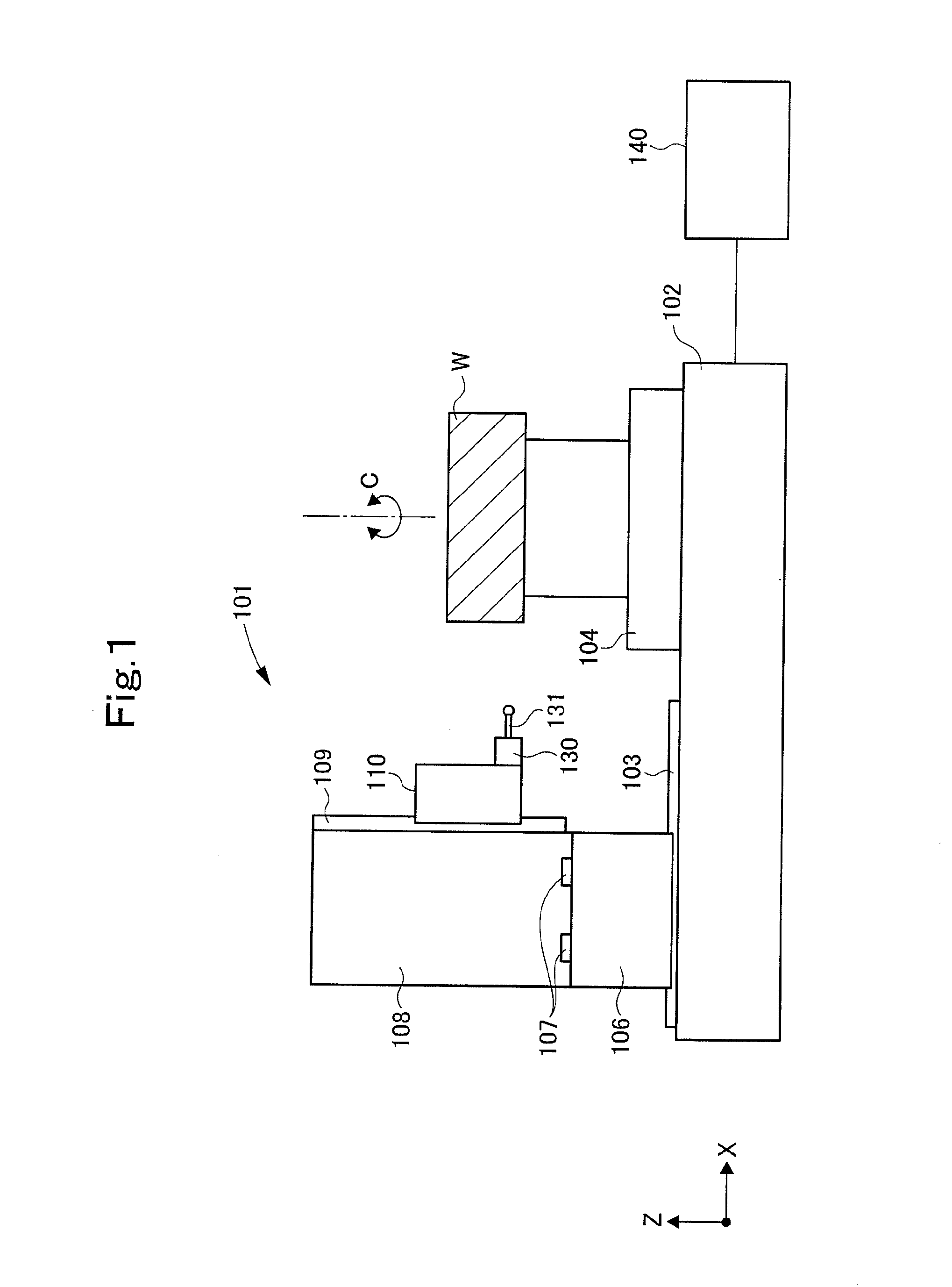
[0058]FIG. 1 shows a gear measuring device 101 to which a method of the present invention is applied. As shown in the drawing, guide rails 103 extending along an X-axis direction and a rotating table 104 are disposed on a base 102 of the gear measuring device 101.

[0059]The rotating table 104 can be rotated about a rotational axis C.

[0060]A movable body 106 can be moved along the X-axis direction along the guide rails 103. Guide rails 107 extending in a Y-axis direction (in FIG. 1, a direction perpendicular to the paper plane) are disposed on the movable body 106, and a movable body 108 can be moved along the Y-axis direction. Guide rails 109 extending along a Z-axis direction (vertical direction) are disposed on the movable body 108, and a movable body 110 can be moved along the Z-axis direction.

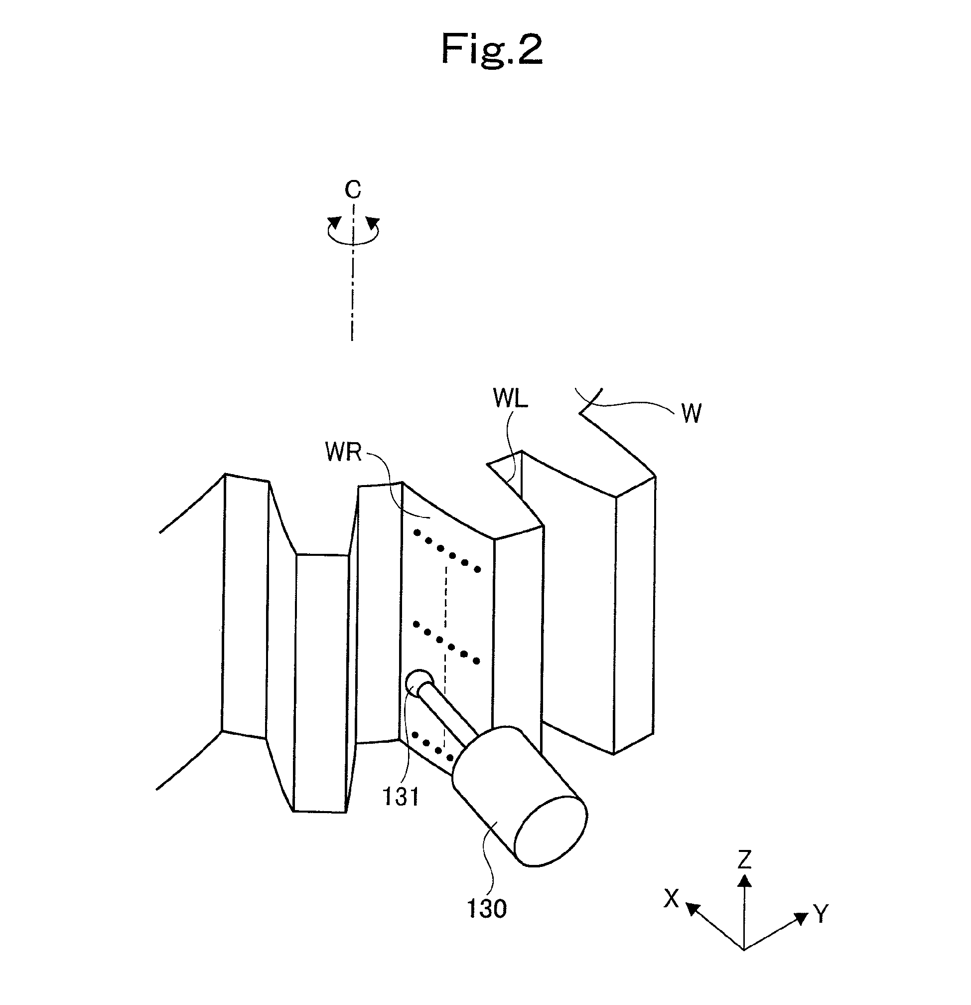
[0061]A measuring instrument 130 provided with a gauge head 131 is attached to the movable body 110. A large ground work (measurement gear, workpiece gear) W (see FIG. 2) is coaxially...


PUM


Abstract

A difference of tooth profile gradient errors (Δα) is calculated, which is a deviation between the tooth profile gradient error (α1) when the tooth profile of a gear is calculated by a method of scanning in a tangential direction of a base circle; and the tooth profile gradient error (α2) when the tooth profile of a gear is calculated by scanning methods other than a method of scanning in a tangential direction of a base circle. The position error (Δx) is calculated using the difference of tooth profile gradient errors (Δα) and gear specifications, and the position of the gauge head is calibrated depending on the position error (Δx). Hereby the position of the gauge head can be calibrated without using a mechanical reference member.

Description

TECHNICAL FIELD[0001]The present invention relates to a method of calibrating a gear measuring device and is designed so that the position of a gauge head can be calibrated without using any mechanical reference member such as a reference block.BACKGROUND ART[0002]A gear processing machine is a machine which processes workpiece gears, and specific examples thereof include a gear profile grinding machine and a hobbing machine, which fabricate gears by cutting processing, and a gear grinding machine, which grinds gears after quenching.[0003]When small workpiece gears are to be processed in mass production by such a gear processing machine, the workpiece gear which is the first processed product is subjected to tooth profile measurement or tooth thickness measurement, and the precision thereof is then checked. If the precision is good, remaining unprocessed lots are processed. If the precision is not good, the remaining unprocessed lots are processed after processing precision is corre...

Claims


Application Information

Patent Timeline
IPC IPC(8): G01B21/16G01B21/20G06F19/00
CPCG01B5/202G01M13/021G01B21/042
Inventor MASUO, KOICHIOTSUKI, NAOHIROYANASE, YOSHIKOTO
Owner MITSUBISHI HEAVY IND MACHINE TOOL CO LTD
Why Eureka
Try Eureka