

Circuit arrangement for operating at least one discharge lamp and at least one LED
- Summary
- Abstract
- Description
- Claims
- Application Information
AI Technical Summary
Benefits of technology
Problems solved by technology
Method used
Image

Examples
Embodiment Construction
[0029]The same reference characters are used below for identical and identically working components. These are therefore only introduced once.
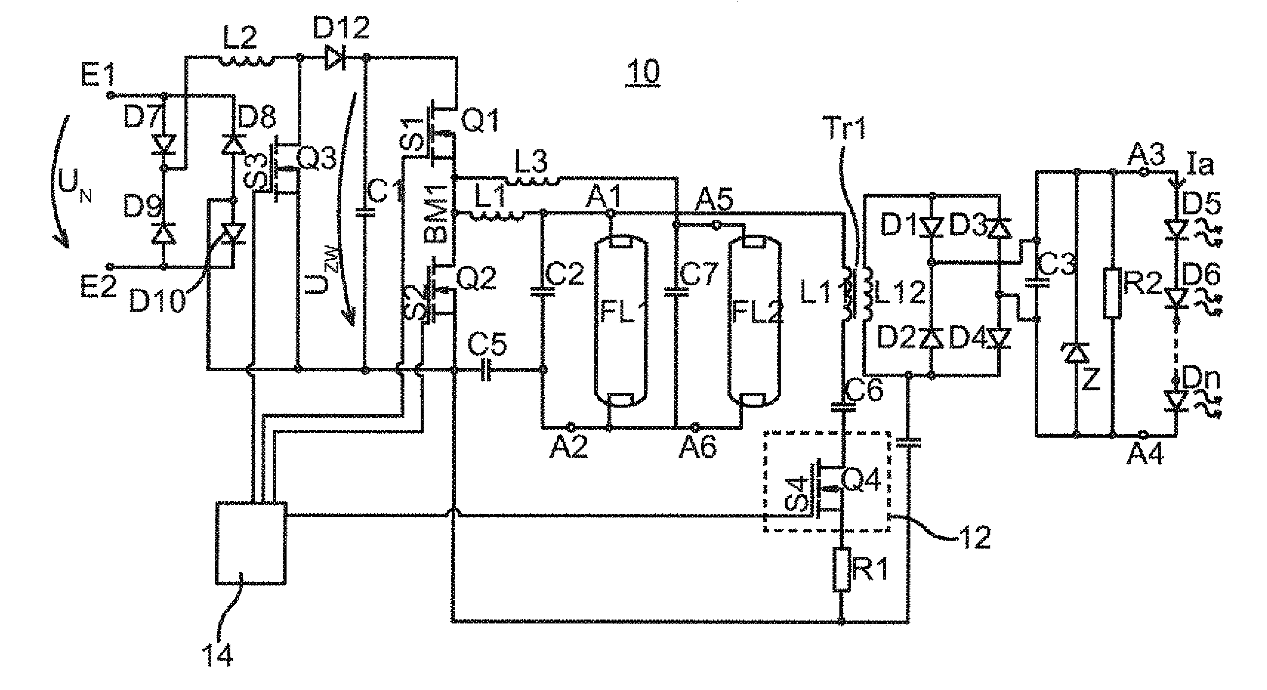
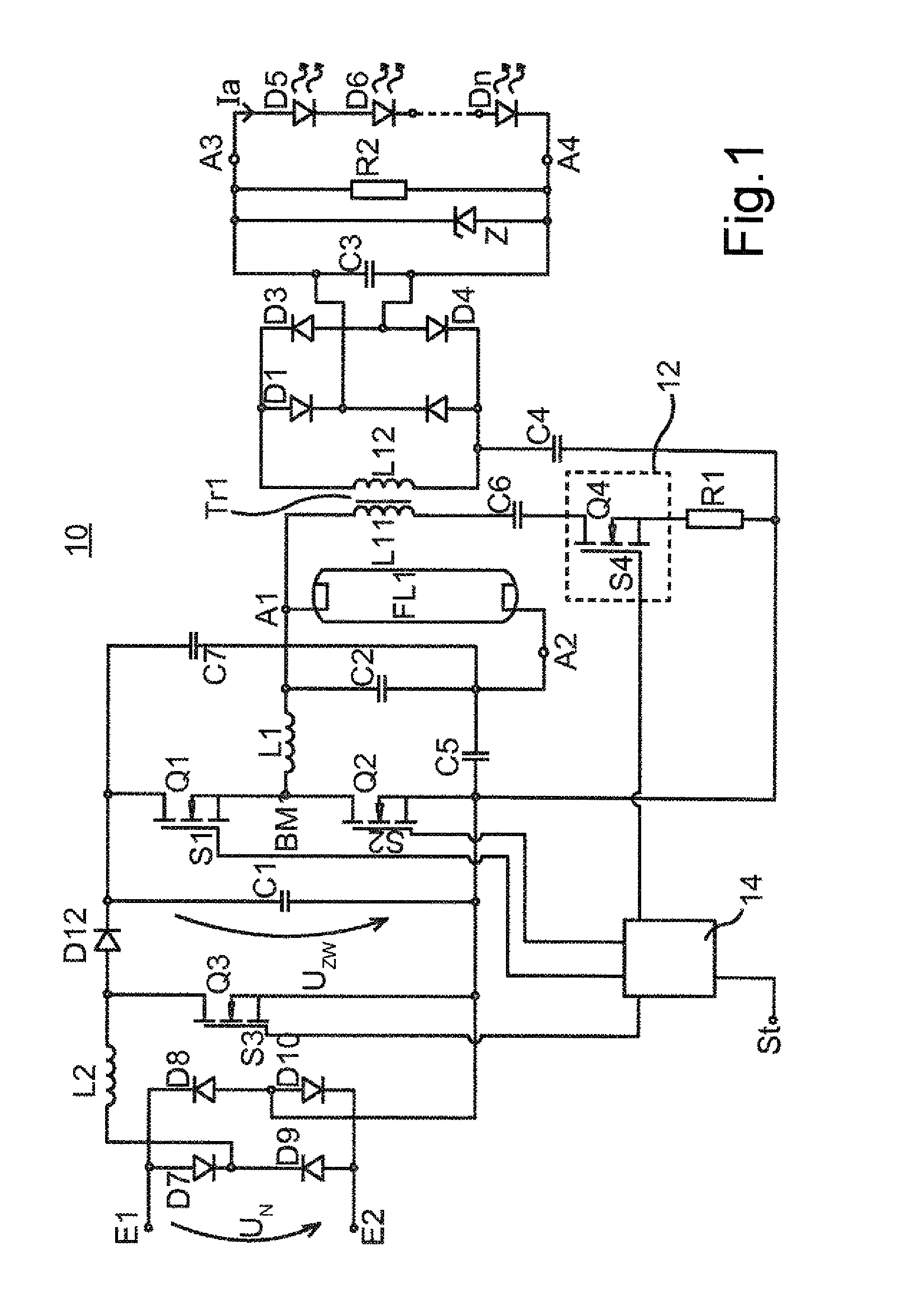
[0030]FIG. 1 shows a first exemplary embodiment of a circuit arrangement according to the invention in a schematic diagram. An alternating current supply voltage UN, in particular a mains voltage, can be connected to an input with a first E1 and a second input connection E2. After that there is a first rectifier including the diodes D7, D8, D9 and D10. A line filter can be located upstream of the rectifier D7 to D10. A boost converter is connected to the rectifier, and includes an inductance L2, a diode D12 and an electronic switch Q3 with a control input S3. The control of boost converters is generally known and is therefore not examined in more detail here.
[0031]The voltage provided at the output of the boost converter is stored in a capacitor C1. The voltage UZw dropping across the capacitor C1 is usually described as intermediate circuit v...
PUM
 Abstract
Description
Claims
Application Information