Reciprocating motor and reciprocating compressor having the same

a reciprocating motor and compressor technology, applied in the direction of motor parameters, piston pumps, dynamo-electric machines, etc., can solve the problems of increased manufacturing costs, difficult manufacturing of inner stators, and excessive expenses, so as to reduce manufacturing costs and facilitate the manufacture of stators.

Active Publication Date: 2013-03-07
LG ELECTRONICS INC
View PDF7 Cites 22 Cited by
  • Summary
  • Abstract
  • Description
  • Claims
  • Application Information

AI Technical Summary

Benefits of technology

[0018]Therefore, an object of the present invention is to provide a reciprocating motor and a reciprocating compressor having the same which make the manufacture of a stator easier and therefore reduce manufacturing costs.

Problems solved by technology

However, the above-mentioned conventional reciprocating motor has the problem that it is difficult to manufacture the inner stator 2 and excessive expenses are required because the stator cores of the inner stator 2 have to be radially laminated.
This may increase the use of the magnet 7, and therefore lead to an increase in manufacturing costs, when compared to the efficiency of the motor.

Method used


Image

  • Reciprocating motor and reciprocating compressor having the same
  • Reciprocating motor and reciprocating compressor having the same
  • Reciprocating motor and reciprocating compressor having the same

Examples


Embodiment Construction

[0037]Hereinafter, a reciprocating motor and a reciprocating compressor according to the present invention will be described in detail with reference to an embodiment illustrated in the accompanying drawings.

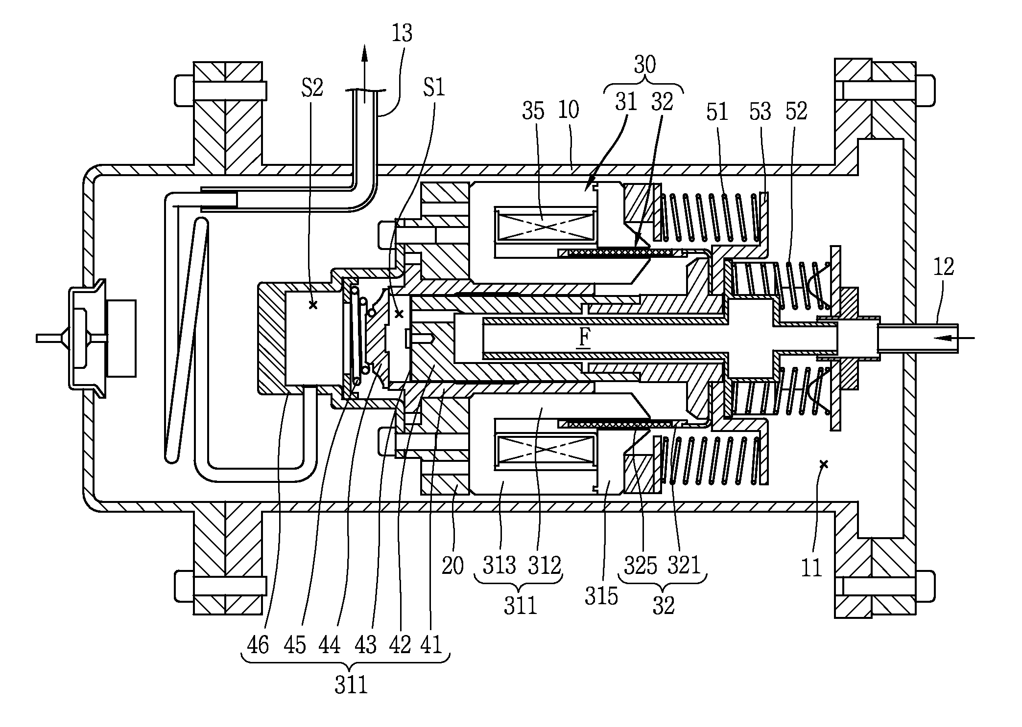
[0038]As shown in FIG. 5, in the reciprocating compressor according to this embodiment, a frame 20 is installed within a sealed casing 10, a reciprocating motor 30 and a cylinder 41 are fixed to the frame 20, and a piston 42 coupled to a mover 32 of the reciprocating motor 30 is inserted into the cylinder 40 to reciprocate.

[0039]A compression space S1 is formed in the cylinder 41, a suction path F is formed in the piston 42, a suction valve 43 for opening and closing the suction path F is installed at a distal end of the suction path F, and a discharge valve 44 for opening and closing the compression space S1 of the cylinder 41 is installed at a front end surface of the cylinder 41.

[0040]In the drawings, unexplained reference numeral 11 denotes an inner space of the casing, 12 d...


PUM


Abstract

A reciprocating motor and a reciprocating compressor having the same make the manufacture of a stator easier and therefore reduce manufacturing costs by configuring the stator such that an inner stator positioned inside the mover and an outer stator positioned outside the mover are integrally formed, or by making the inner and outer circumferential surfaces of the stator have the same curvature. Also, no gap is generated between the inner stator and the outer stator, and this prevents magnetic leakage, thereby improving the performance of the motor. Also, the use of magnets can be reduced by omitting magnets between stator blocks, and therefore manufacturing costs can be reduced, when compared to the efficiency of the motor.

Description

CROSS-REFERENCE TO RELATED APPLICATION[0001]The present disclosure relates to subject matter contained in priority Korean Application No. 10-2011-0090317, filed on Sep. 6, 2011, which is herein expressly incorporated by reference in its entirety.BACKGROUND OF THE INVENTION[0002]1. Field of the Invention[0003]The present disclosure relates to a reciprocating motor and a reciprocating compressor having the same.[0004]2. Background of the Invention[0005]Generally, a reciprocating compressor serves to intake, compress, and discharge a refrigerant as a piston linearly reciprocates within a cylinder. The reciprocating compressor may be classified into a connection type reciprocating compressor or a vibration type reciprocating compressor according to the method employed to drive the piston.[0006]In the connection type reciprocating compressor, the piston is connected to a rotating shaft associated with a rotation motor by a connection rod, which causes the piston to reciprocate within the...

Claims


Application Information

Patent Timeline
Patent Type & Authority Applications(United States)
IPC IPC(8): F04B35/04H02K33/00
CPCF04B35/045H02K33/04H02K33/06F04B17/04H02K33/02F04B2203/0403
Inventor HONG, EONPYO
Owner LG ELECTRONICS INC
Why Eureka
Try Eureka