Regulator valve fault checking method

a regulator valve and fault technology, applied in the direction of testing/monitoring control systems, instruments, nuclear elements, etc., can solve the problems of inability to check for faults in the regulator valve well, incorrect diagnosis, and disturbance of balan

Active Publication Date: 2013-03-07
YAMATAKE HONEYWELL CO LTD
View PDF2 Cites 10 Cited by
  • Summary
  • Abstract
  • Description
  • Claims
  • Application Information

AI Technical Summary

Benefits of technology

[0020]In the present disclosure, the input signal into the regulator valve and the valve opening, as an output from the regulator valve, are sampled periodically, the speed of change of the input signal that is sampled and the speed of change of the valve opening that is sampled are calculated, a weighting is calculated in accordance with a combination of the speed of change of the input value and the speed of change of the valve opening, based on a weighting function that is established in advance, and fault checking

Problems solved by technology

When a fluid reactive force is produced, that balance is disrupted.
However, in the regulator valve fault checking method set forth above, when performing fault checking of the regulator valve using data from the processing operation during processing operations, in some cases it is not possible to check well for faults in the regulator valve.
Because of this, there will be an incorrect diagnosis that there is a fault in the regulator valve.
Because of

Method used


Image

  • Regulator valve fault checking method
  • Regulator valve fault checking method
  • Regulator valve fault checking method

Examples


first embodiment

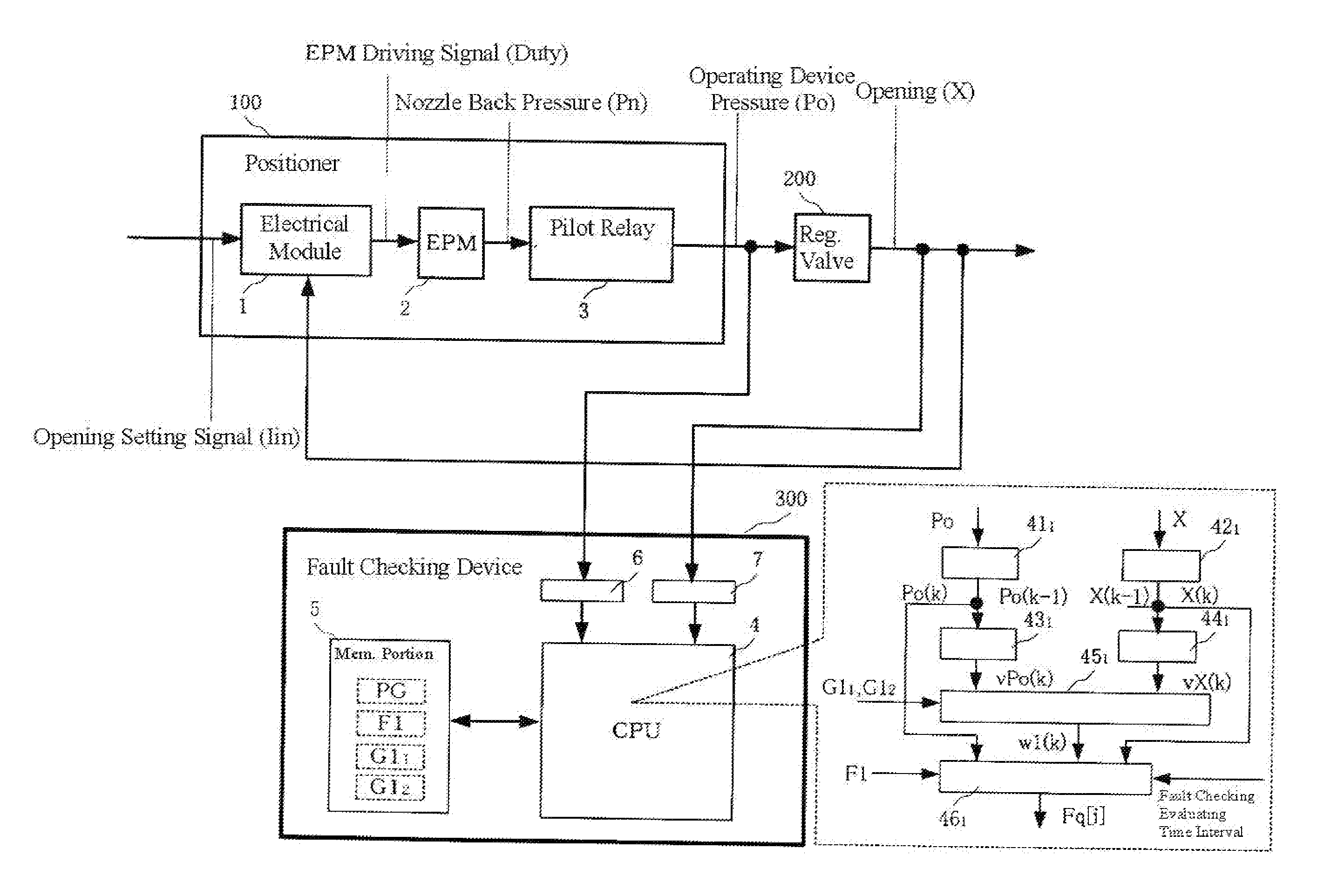
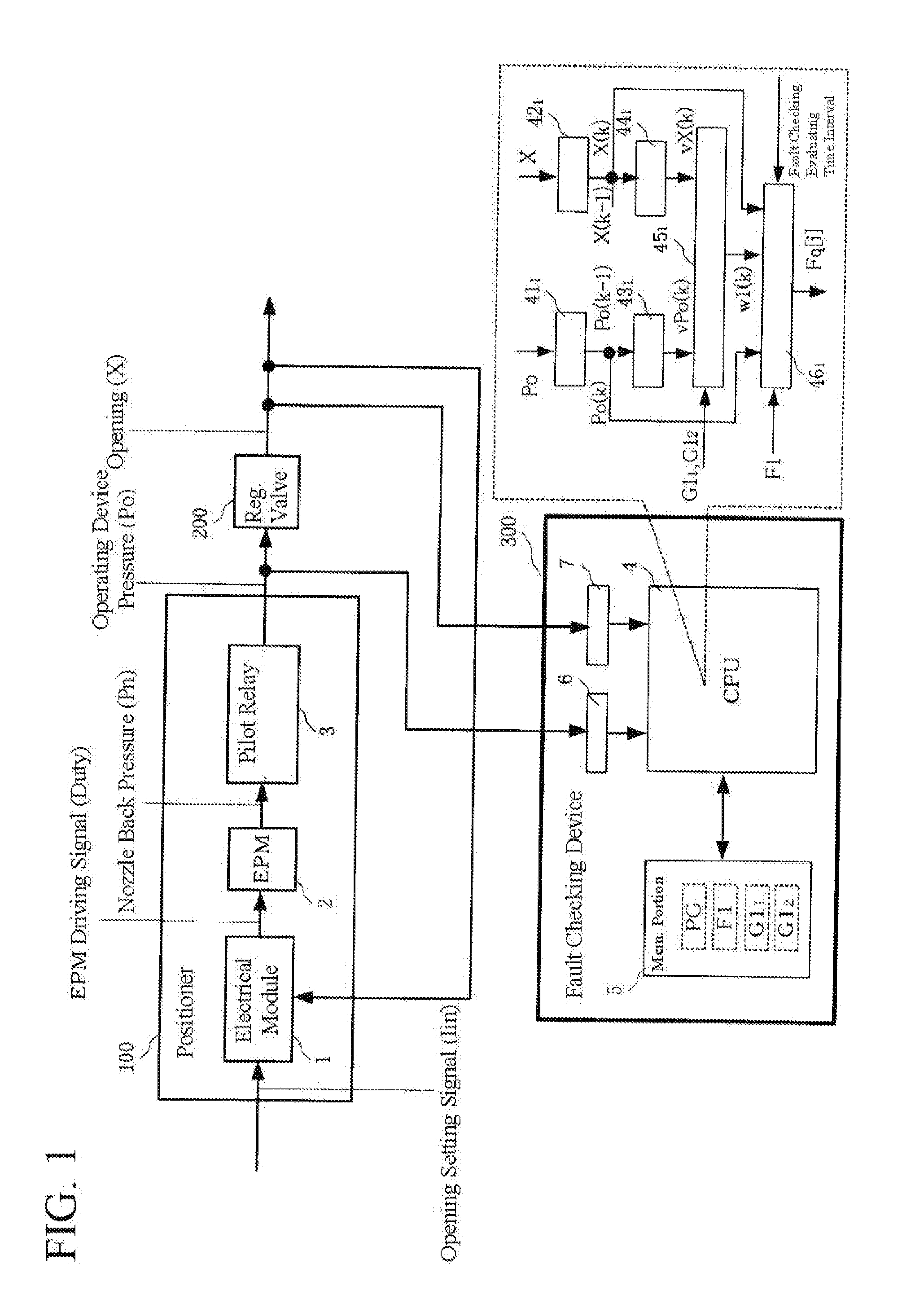
[0050]FIG. 1 shows the structure of the critical portions of a fault checking device 300 for performing a fault check of a regulator valve 200 with the flow reactive force as the fault check indicator value. This fault checking device 300 includes a CPU 4, a memory portion 5 that is a ROM, a RAM, or the like, and interfaces 6 and 7. Note that this fault checking device 300 may be provided within a positioner 100 or a regulator valve 200, or may be provided outside of the positioner 100 and the regulator valve 200. FIG. 1 shows an example wherein it is provided on the outside of the positioner 100 and the regulator valve 200.

[0051]The operating device pressure Po that is the input signal into the regulator valve 200 is branched and inputted through the interface 6 into the CPU 4, and the degree of opening X, which is the output from the regulator valve 200, is branched and inputted through the interface 7 into the CPU 4. The CPU 4 operates in accordance with a program PG that is stor...

second embodiment

[0096]FIG. 14 shows the structure of the critical components of a fault checking device 400 for performing fault checking for a regulator valve 200 using a value for the hysteresis width as the fault check indicator value. In the fault checking device 400 as well, as with the first embodiment, a CPU 4, a memory portion 5, such as a ROM or a RAM, and interfaces 6 and 7 are provided. Note that this fault checking device 400 may also be provided within the positioner 100 or the regulator valve 200, or may be provided outside of the positioner 100 and the regulator valve 200. FIG. 14 shows an example wherein it is provided outside of the positioner 100 and the regulator valve 200.

[0097]The operating device pressure Po that is the input signal into the regulator valve 200 is branched and inputted through the interface 6 into the CPU 4, and the degree of opening X, which is the output from the regulator valve 200, is branched and inputted through the interface 7 into the CPU 4. The CPU 4 ...


PUM


Abstract

An operating device pressure Po into a regulator valve and a degree of opening X from the regulator valve are sampled. A speed of change vPo (k) of the Po (k) is calculated from the current Po (k) and the previous Po (k-1). A speed of change vX (k) of the X (k) is calculated from the current X (k) and the previous X (k-1). If both vPo (k) and vX (k) are small, then a weighting value w1 (k) is set to 1 (and set to 0 otherwise), where a fault check indicator Fq (i) for each degree-of-opening category i during a fault check evaluation time interval is calculated from the vPo (k) and vX (k) when w1 (k) is 1 and from a linear approximation formula F1 that indicates the steady-state input/output relationships in the regulator valve when operating properly.

Description

CROSS-REFERENCE TO RELATED APPLICATION[0001]The present application claims priority to Japanese patent application No. 2011-191313 filed on Sep. 2, 2011, the entire content of which is hereby incorporated by reference.TECHNICAL FIELD[0002]The present disclosure relates to a method and device for checking for faults in regulator valves for regulating the flows of fluids.RELATED ART[0003]Conventionally, in chemical plants, and like, positioners have been provided in regulator valves used in the flow rate processes thereof, to adjust the opening of regulator valves using the positioners. The positioner would be provided with a calculating portion for calculating the difference between an opening setting value sent from a higher-level device and an actual opening value, fed back from the regulator valve, to generate an electric signal, as a control output, in accordance with this difference, an electro-pneumatic converting device for converting, into an air pressure signal, the control ...

Claims


Application Information

Patent Timeline
IPC IPC(8): G06F15/00
CPCF16K37/0083G05B23/0243
Inventor KASHIMA, TORU
Owner YAMATAKE HONEYWELL CO LTD
Why Eureka
Try Eureka