Operation input device and manipulator system

a technology of which is applied in the field of operation input device and manipulator system, can solve the problems of time-consuming, complicated computation of coordinate transformation, and limited area in which the device can move, and achieve the effect of reducing calculation costs and simple configuration

Active Publication Date: 2013-03-14
OLYMPUS CORP
View PDF3 Cites 46 Cited by
  • Summary
  • Abstract
  • Description
  • Claims
  • Application Information

AI Technical Summary

Benefits of technology

[0007]An object of the present invention is to provide an operation input device and a manipulator system with which, with a simple configuration, an area in which an operating unit can move can be prevented from being limited.

Problems solved by technology

However, with a method in which the positions and orientations of a display and an operating unit are detected by spatial sensors provided on a ceiling, although these devices can be employed in a dedicated room in which there is no obstacle between the ceiling and both the display and the operating unit, it is difficult to employ them in a operating theatre where equipment that acts as an obstacle exists, such as an illumination apparatus, a measuring instrument or the like, and thus, there is a case in that the areas in which the devices can move are limited.
With the method in the related art, by obtaining information about the positions and the orientations of the display and the operating unit, each having its own coordinate system, by means of the spatial sensors secured to the ceiling, the relative positional relationship between the display and the operating unit is obtained from the information about the positions and the orientations of the display and the operating unit in the respective spatial-sensor coordinate systems, computations involved in the coordinate transformations are complicated and time consuming.

Method used


Image

  • Operation input device and manipulator system
  • Operation input device and manipulator system
  • Operation input device and manipulator system

Examples


Embodiment Construction

[0034]An operation input device and a manipulator system according to an embodiment of the present invention will be described below with reference to the drawings.

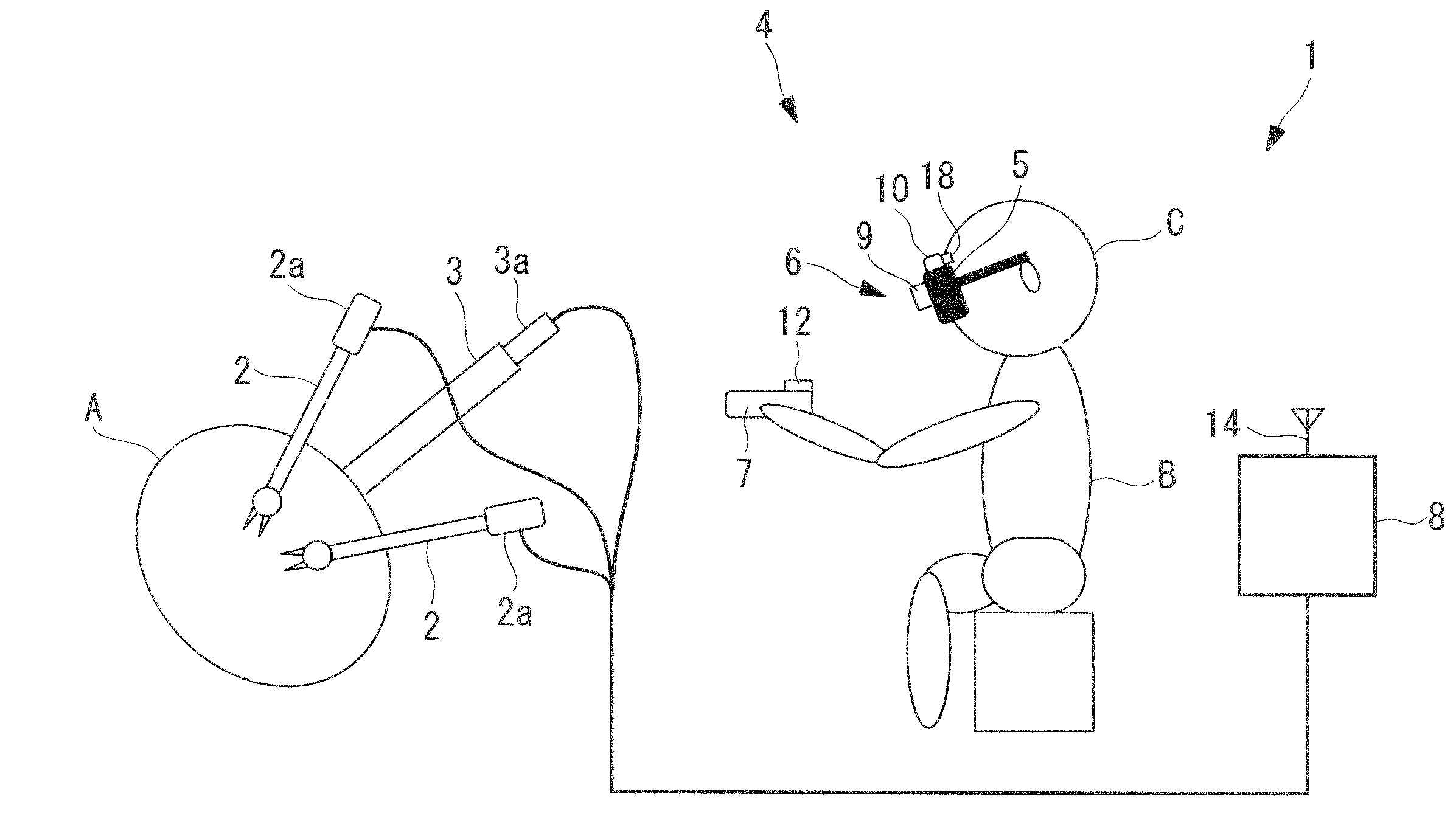
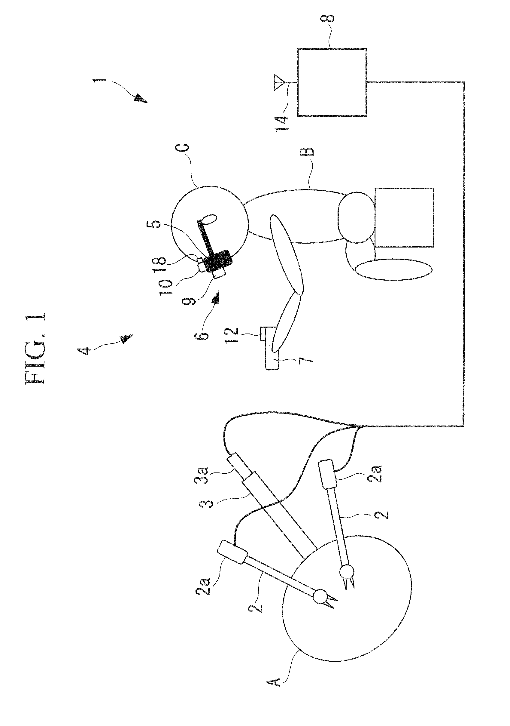
[0035]As shown in FIG. 1, a manipulator system 1 according to this embodiment is provided with a manipulator 2 that is inserted into the body of a patient A, an endoscope (observation device) 3 that captures a video image of the manipulator 2, and an operation input device 4 according to this embodiment.

[0036]In the example shown in FIG. 1, two manipulators 2 are provided, for each of which the orientation, position, and actuation status thereof can be individually changed by means of a motor 2a. Also, the orientation, position, and actuation status of the endoscope 3 can be changed by means of a motor 3a.

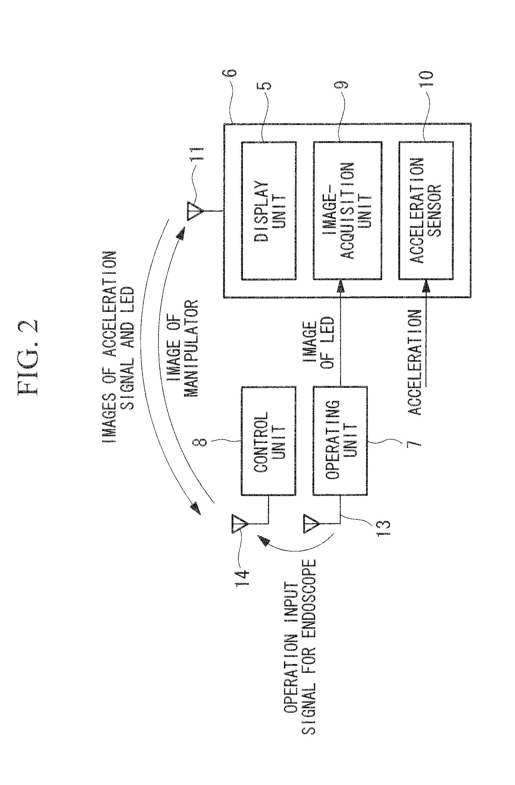
[0037]The operation input device 4 according to this embodiment is provided with a display unit (display) 5 that displays a video image of the manipulators 2 obtained by the endoscope 3 inside the body of the patient A,...


PUM


Abstract

With a simple configuration, a area in which an operating unit can move is prevented from being limited. Provided is an operation input device including a display; an operating unit that operates a display object displayed on the display; a head-mounted unit that is mounted on the head of an operator; relative position sensors that detect a relative position and a relative orientation of one of the head-mounted unit and the operating unit with respect to the other; and a control unit that actuates the display object displayed on the display on the basis of changes in the relative position and the relative orientation detected by the relative position sensors.

Description

CROSS REFERENCE TO RELATED APPLICATIONS[0001]This is a continuation of International Application PCT / JP / 2011 / 055050, with an international filing date of Mar. 4, 2011, which is hereby incorporated by reference herein in its entirety. This application is based on Japanese Patent Application No. 2010-108344, the content of which is incorporated herein by reference.BACKGROUND OF THE INVENTION[0002]1. Field of the Invention[0003]The present invention relates to an operation input device and a manipulator system.[0004]2. Description of Related Art[0005]In the related art, there is a known virtual-experience gaming device in which a sensor for detecting the positions of a display and an operating unit is provided on a ceiling (for example, see Japanese Unexamined Patent Application, Publication No. 2000-126462).[0006]However, with a method in which the positions and orientations of a display and an operating unit are detected by spatial sensors provided on a ceiling, although these device...

Claims


Application Information

Patent Timeline
Patent Type & Authority Applications(United States)
IPC IPC(8): G09G3/00G06F3/033G06F3/0346
CPCA61B19/2203G09G3/001A61B2019/2269A61B2019/262A61B2019/5214A61B2019/5248A61B2019/5255A61B2019/5257A61B2019/5297B25J9/1689B25J13/02G05B2219/35482G05B2219/45117G06F3/011G06F3/012A61B1/00A61B19/5244A61B2090/502A61B2090/3612A61B2034/2048A61B2034/2055A61B2034/2057A61B2090/368A61B34/20A61B34/30A61B34/74
Inventor OGAWA, RYOHEIKISHI, KOSUKE
Owner OLYMPUS CORP
Why Eureka
Try Eureka