Distance estimation using sound signals

a technology of distance estimation and sound signals, applied in the direction of loudspeakers, using reradiation, instruments, etc., can solve the problems of unsatisfactory amount of effort on the part of users, subject to user error, and conventional loudspeaker arrays can only produce highly directional sound beams over a limited frequency range, so as to improve sound reproduction

Active Publication Date: 2013-03-14
KONINKLIJKE PHILIPS ELECTRONICS NV
View PDF1 Cites 46 Cited by
  • Summary
  • Abstract
  • Description
  • Claims
  • Application Information

AI Technical Summary

Benefits of technology

[0024]This may provide additional information that may allow improved and/or extended functionality. For example, when used to determine or estimate an audio environment geometry, it may allow a more accurate determination of the geometry and thus an improved sound reproduction based thereon. Additionally or alternatively it may allow or assist in object identification in the audio environment.
[0025]In p

Problems solved by technology

Since it is not possible in advance to account for every possible permutation of room size, sound system location and listener position etc, it is in practice only possible to provide a limited number of preset options.
While it is possible to measure this data manually, this would represent an undesirable amount of effort on the part of the user, and would be subject to user error.
A conventional loudspeaker array can only produce highly directional sound beams over a limited range of frequencies determined by the width of the array and the spacing of the loudspeakers.
The limited bandwidth results in the disclosed system using a single frequency test tone for the calibration which may result in e.g. reduced signal to noise ratio compared to wider bandwidth signals.
The disclosed system may also be prone to lobbing artefacts which can give rise to spurious results.
Another problem faced by the use of a conventional loudspeaker array is that the large aperture required for high directivity also results in a large audio

Method used


Image

  • Distance estimation using sound signals
  • Distance estimation using sound signals
  • Distance estimation using sound signals

Examples


Embodiment Construction

[0064]The following description focuses on embodiments of the invention applicable to a calibration of a spatial sound reproduction system based on an audio environment geometry determined from distance measurements. However, it will be appreciated that the invention is not limited to this application but may be applied in many other scenarios and for many other applications.

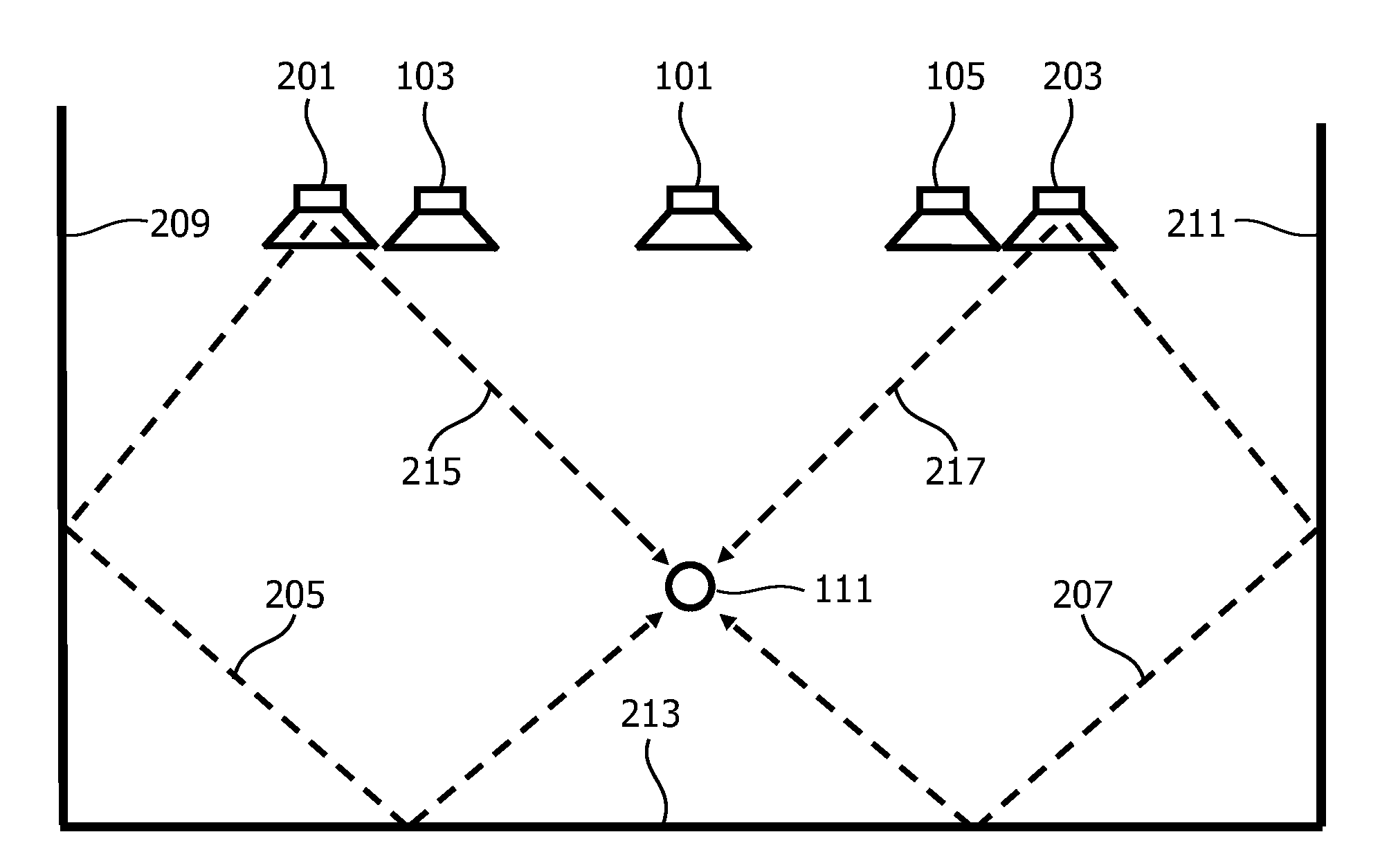
[0065]FIG. 1 illustrates a speaker system setup for a conventional five channel surround sound spatial sound reproduction system, such as a home cinema system. The system comprises a center speaker 101 providing a center front channel, a left front speaker 103 providing a left front channel, a right front speaker 105 providing a right front channel, a left rear speaker 107 providing a left rear channel, and a right rear speaker 109 providing a right rear channel. The five speakers 101-109 together provide a spatial sound experience at a listening position 111 and allow a listener at this location to experience a...


PUM


Abstract

An apparatus comprises a test signal generator (401) which generates an ultrasonic test signal by modulating an audio band test signal on an ultrasonic signal. The ultrasonic test signal is radiated from a parametric loudspeaker (403) and is demodulated by non-linearities in the air. A reflected audio signal may arise from reflections of an object, such as a wall. An audio band sensor (405) generates an audio band captured signal which comprises the demodulated reflected audio band signal. A distance circuit (407) then generates a distance estimate for the distance from the parametric loudspeaker (403) to the object in response to a comparison of the audio band captured signal and the audio band test signal. Specifically two signals may be correlated to determine a delay corresponding to the full path length. Based on the distance estimates an audio environment may be estimated and a sound system may be adapted accordingly.

Description

FIELD OF THE INVENTION[0001]The invention relates to estimation of distances to objects and in particular but not exclusively to characterisation of audio environments based on estimation of distances.BACKGROUND OF THE INVENTION[0002]Automated determination of distances is important for many applications. For example, the audio environment greatly affects the performance of a loudspeaker system, and e.g. the acoustics of a room significantly affect the spatial experience that can be provided by a spatial sound reproduction system. To provide the best possible spatial rendering it is therefore important that the sound reproduction system be properly calibrated to the specific audio environment. Since it is not possible in advance to account for every possible permutation of room size, sound system location and listener position etc, it is in practice only possible to provide a limited number of preset options. A proper calibration of a sound reproduction system must therefore be carr...

Claims


Application Information

Patent Timeline
IPC IPC(8): G01S15/08
CPCG01S7/524G01S15/89G01S15/32G01S7/534H04R3/12H04R2203/12H04R2217/03H04S7/301
Inventor AARTS, RONALDUS MARIALAMB, WILLIAM JOHN
Owner KONINKLIJKE PHILIPS ELECTRONICS NV
Why Eureka
Try Eureka