

Optical disc apparatus
a technology of optical discs and optical discs, applied in the field of optical disc apparatuses, can solve the problems of increasing errors, reducing optical spot errors, and reducing the influence of defects
- Summary
- Abstract
- Description
- Claims
- Application Information
AI Technical Summary
Benefits of technology
Problems solved by technology
Method used
Image

Examples
embodiment 1
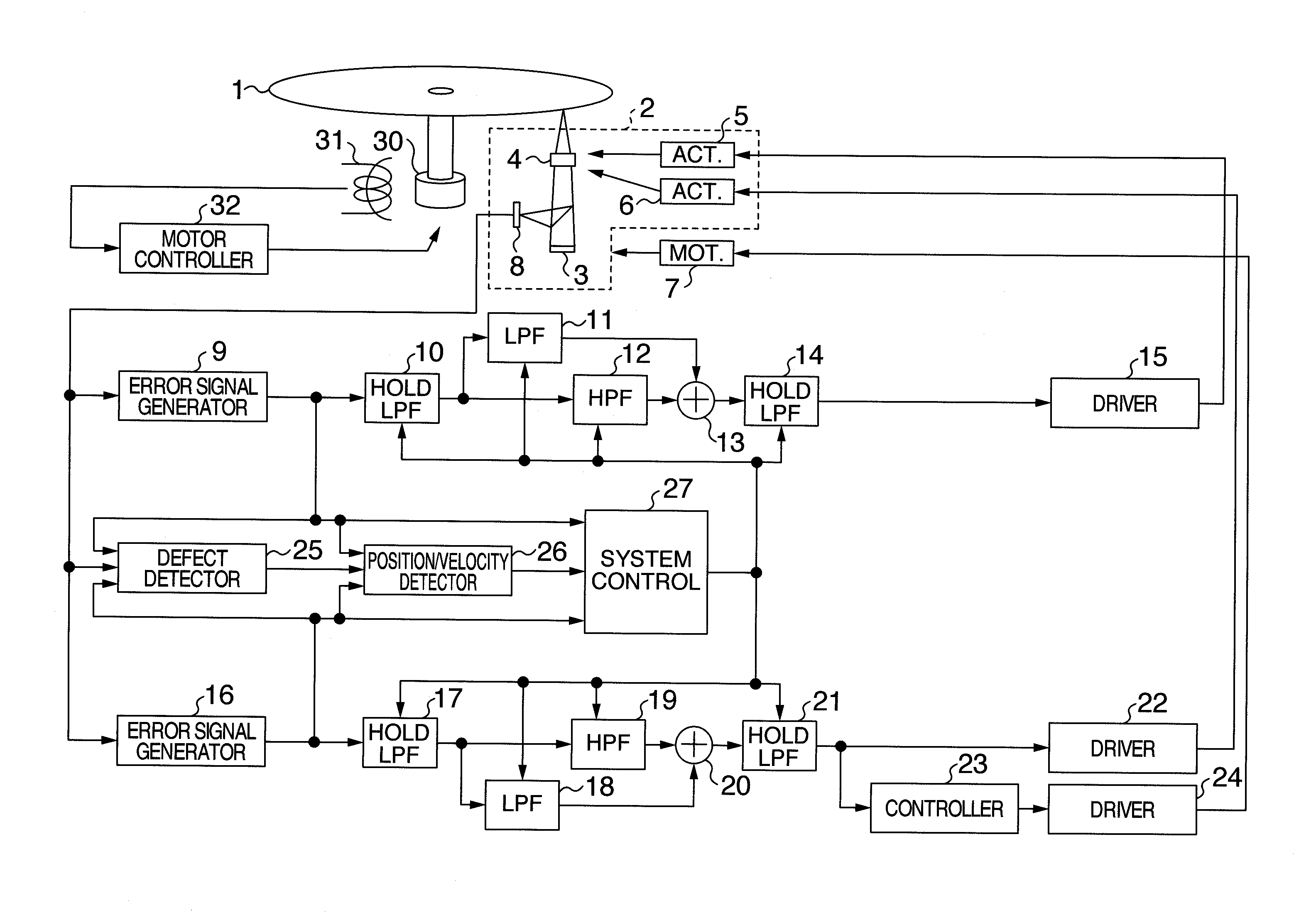
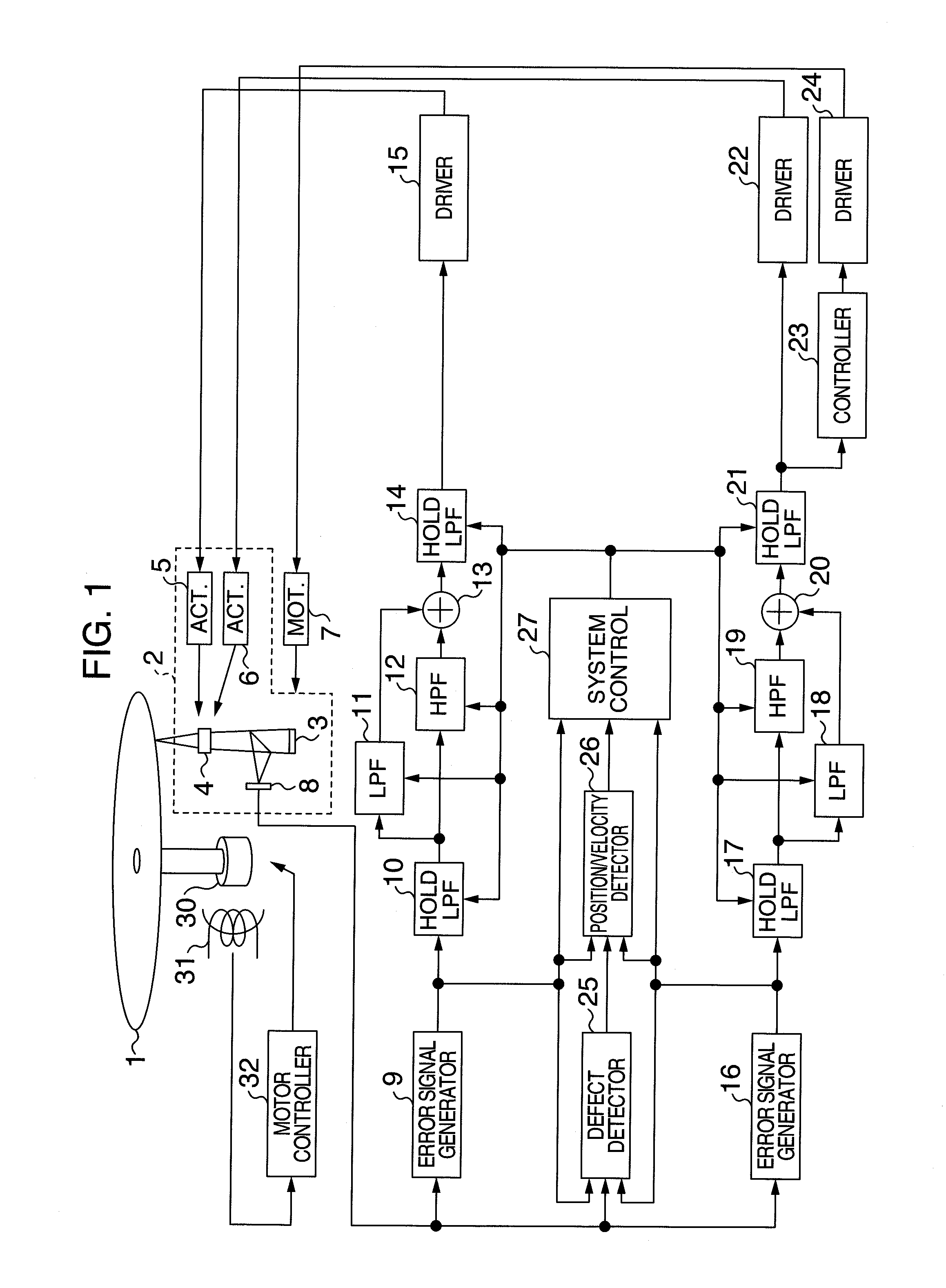
[0023]FIG. 1 is a block diagram of an arrangement of an optical disc apparatus according to Embodiment 1. In FIG. 1, reference numeral 1 denotes a disc, numeral 2 denotes an optical pickup unit, 3 a laser diode, 4 an objective lens, 5 a focus actuator, 6 a tracking actuator, 7 a pickup feeding motor, 8 a detector, 9 a focus error signal generating module, 10 a holding module, 11 an LPF (low-pass filter) for low frequency component compensation, 12 a HPF for phase compensation, 13 an adder, 14 a holding module, 15 a focus actuator driving module, 16 a tracking error signal generating module, 17 a holding module, 18 an LPF for low frequency component compensation, 19 an HPF for phase compensation, 20 an adder, 21 a holding module, 22 a tracking actuator driving module, 23 a feed motor control module, 24 a feed motor driving module, 25 a defect detecting module, 26 a position / velocity detecting module, 27 a system controller, 30 a spindle motor for rotating the disc, 31 a frequency gen...
embodiment 2
[0043]Although the initial value to be in the compensator after the defect passage is calculated on the basis of the position and velocity of the optical spot in the above embodiment; similar effects to the above case can be obtained also by previously storing the output of the compensator or the output of the internal calculation when the optical spot passed over the defect and by calculating the initial value on the basis of the stored value.
[0044]Explanation will then be made as to the arrangement of an optical disc apparatus in accordance with the present invention with reference to FIG. 6. In FIG. 6, since the blocks 1 to 27 and 30 to 32 are substantially the same as those in the embodiment 1, explanation about such blocks is omitted. In FIG. 6, a reference numeral 28 denotes a memory module.
[0045]The operations of the system controller 27 and memory module 28 different from the embodiment 1 wlll be explained. The system controller 27 receives a defect detection signal from the...
embodiment 3
[0051]In the above embodiment, the initial value of the compensator is calculated from the values of the delay memory stored in the past, and a temporary initial value is set in the compensator when there is no corresponding value of the delay memory stored in the past. However, when there is no corresponding value in the delay memory stored in the past, the control error generated by the defect passage can be quickly reduced even by calculating a focus position correction pulse or a track position correction pulse on the basis of the position and velocity of the optical spot after the defect passage, which will be explained later.
[0052]Explanation will be made as to the arrangement of another optical disc apparatus according to the present invention by using FIG. 9. In the drawing, blocks 1 to 32 are similar to those in the embodiments 1 and 2, and thus explanation thereof is omitted. In FIG. 9, a reference numeral 33 denotes an adder, and a numeral 34 denotes an adder.
[0053]Explan...
PUM
 Abstract
Description
Claims
Application Information