Gas delivery and distribution for uniform process in linear-type large-area plasma reactor

a plasma reactor and linear-type technology, applied in the direction of dental surgery, lighting and heating equipment, combustion types, etc., can solve the problems of compromising the uniformity of gas feed, blocking the flow of gas into the processing volume, and challenging uniformity along the lines, so as to achieve the effect of small siz

Inactive Publication Date: 2013-03-21
APPLIED MATERIALS INC
View PDF3 Cites 20 Cited by
  • Summary
  • Abstract
  • Description
  • Claims
  • Application Information

AI Technical Summary

Benefits of technology

[0013]In yet another embodiment, a processing chamber is provided comprising a gas source, a plasma source, a vacuum pump, a substrate support, and at least one gas distribution tube fluidically coupled to the gas source, wherein a source gas is fed into at least one portion of the gas distribution tube, and wherein the gas distribution tube has apertures which are smaller in size the closer the aperture is to the at least one portion of the gas distribution tube where the source gas is fed. The at least one gas distribution tube may further comprise an outer tube surrounding the gas distribution tube, wherein the outer tube has apertures larger than the apertures of the gas distribution tube. In another embodiment, the at least one gas distribution tube may be fluidically connected to a vacuum line coupled to the vacuum pump.

Problems solved by technology

Uniformity along the lines, however, is also challenging and especially critical for cases when the lines are over one meter long, which includes many next-generation display and solar tools.
Another challenge to uniform gas distribution is the clogging of the apertures in gas distribution tubes as process residues deposit around the openings, blocking the flow of gas into the processing volume.
While larger holes in the tube are less prone to clogging, they compromise the uniformity of the gas feed by contributing to the pressure drop along the gas tube.
This causes the flow of gas into the processing chamber to be non-uniform.
If smaller holes are used, the holes contribute less to the pressure drop along the gas feed tube but clog more easily.

Method used


Image

  • Gas delivery and distribution for uniform process in linear-type large-area plasma reactor
  • Gas delivery and distribution for uniform process in linear-type large-area plasma reactor
  • Gas delivery and distribution for uniform process in linear-type large-area plasma reactor

Examples


Embodiment Construction

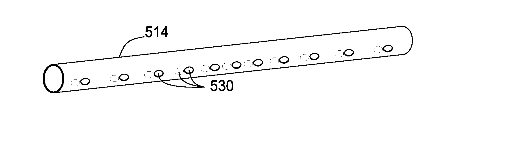
[0026]Embodiments of the present invention generally relate to gas distribution tubes for providing a gas into a processing region, including gas distribution tube geometry and gas-injection hole distribution along the tube so that reactive gases can be fed into the area between the gas distribution tube and substrate uniformly along the length of the tube. Embodiments described herein can provide substantially equal gas flow such as no greater than 20% difference in flow per twelve inches of gas distribution tube length, with further embodiments of less than 10% difference in flow per six inches of gas distribution tube length.

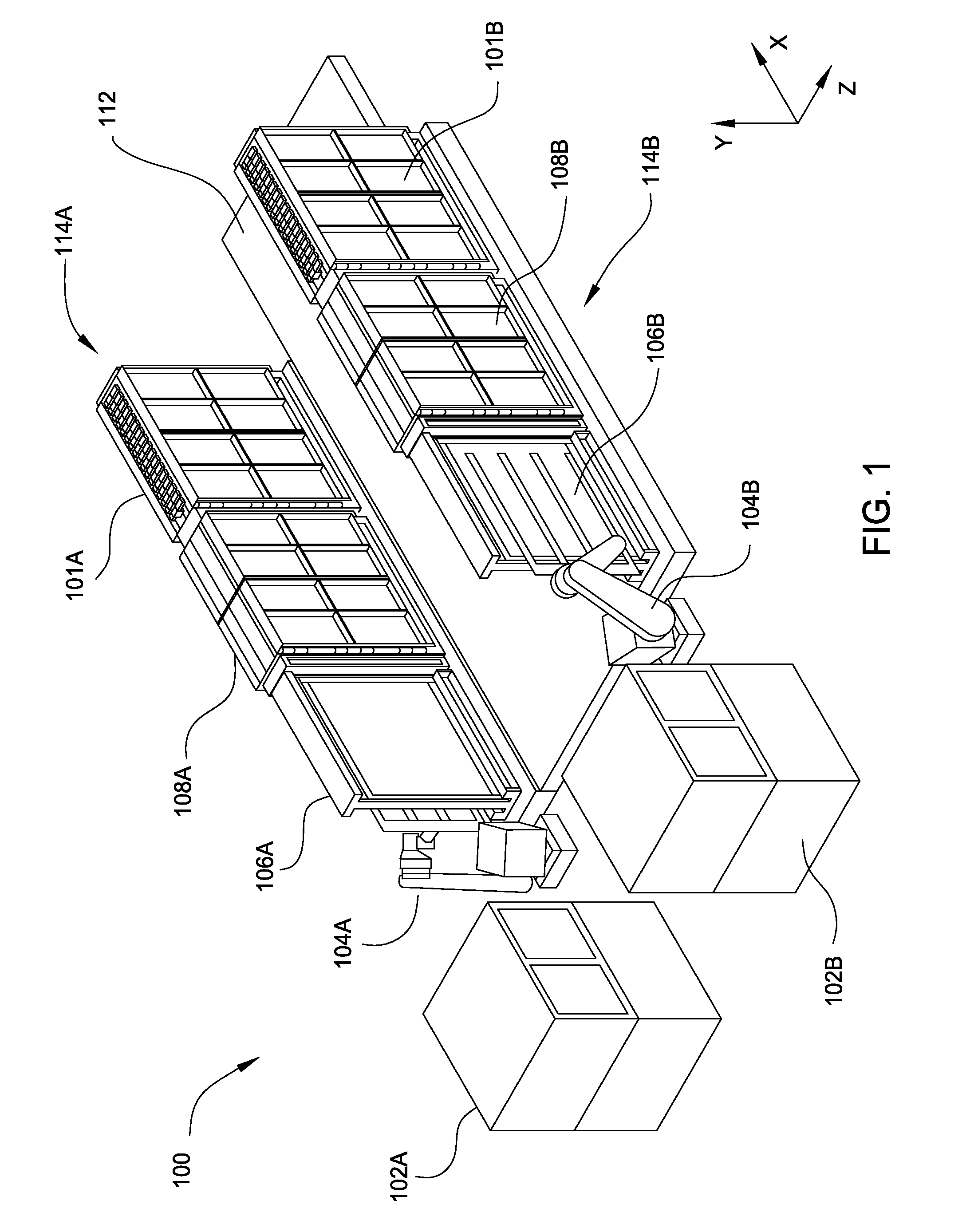
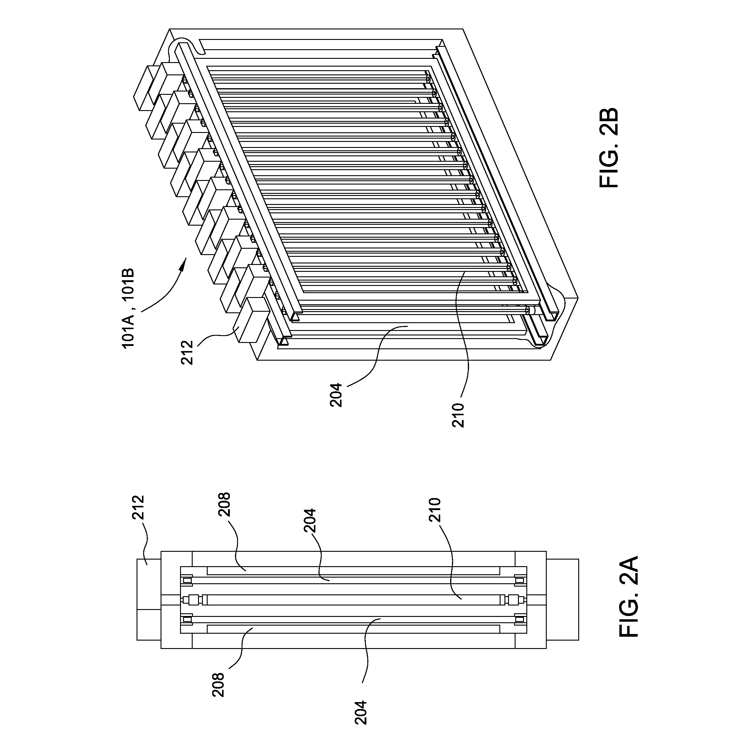
[0027]In one embodiment, gas distribution tubes disposed between plasma lines and a substrate may have a small cross-section in order to minimize plasma shadowing. In other embodiments, the spacing of gas-injection holes along the gas distribution tubes may be larger at sections of the tubes where less gas outflow (and less pressure drop) is desired (such as ...


PUM

PropertyMeasurementUnit
lengthaaaaaaaaaa
lengthaaaaaaaaaa
surface areaaaaaaaaaaa

Abstract

An apparatus for introducing gas into a processing chamber comprising one or more gas distribution tubes having gas-injection holes which may be larger in size, greater in number, and/or spaced closer together at sections of the gas introduction tubes where greater gas conductance through the gas-injection holes is desired. An outside tube having larger gas-injection holes may surround each gas distribution tube. The gas distribution tubes may be fluidically connected to a vacuum foreline to facilitate removal of gas from the gas distribution tube at the end of a process cycle.

Description

CROSS-REFERENCE TO RELATED APPLICATIONS[0001]This application claims benefit of U.S. Provisional Patent Application Ser. No. 61 / 535,207 (APPM / 16390L), filed Sep. 15, 2011, which is herein incorporated by reference.BACKGROUND OF THE INVENTION[0002]1. Field of the Invention[0003]Embodiments of the present invention generally relate to gas distribution tubes for providing a gas into a processing region.[0004]2. Description of the Related Art[0005]Plasma sources used in display and thin-film solar plasma enhanced chemical vapor deposition (PECVD) tools are typically parallel-plate reactors using capacitively coupled RF or VHF fields to ionize and dissociate process gases between plate electrodes. Next-generation flat-panel PECVD chambers include plasma reactors capable of processing two substrates at the same time by having two substrates in one “vertical” chamber and using “common” plasma and gas sources between the substrates. This approach not only increases the throughput of the sys...

Claims


Application Information

Patent Timeline
Patent Type & Authority Applications(United States)
IPC IPC(8): C23C16/455B05B1/14
CPCC23C16/45578C23C16/54C23C16/511C23C16/4587C23C16/455C23C16/513
Inventor WHITE, JOHN M.ANWAR, SUHAILKUDELA, JOZEFSORENSEN, CARL A.WON, TAE K.CHO, SEON-MEECHOI, SOO YOUNGPARK, BEOM SOOJOHNSTON, BENJAMIN M.
Owner APPLIED MATERIALS INC
Why Eureka
Try Eureka