
Self-controlled inflow control device

a self-controlled, control device technology, applied in the direction of fluid removal, sealing/packing, borehole/well accessories, etc., can solve the problems of limiting the production area, preventing the production of fluid from the entire reservoir profile to the surface, and completely stopping production, so as to reduce the flow of reservoir fluid and balance the production profile

Active Publication Date: 2013-03-21
SAUDI ARABIAN OIL CO
View PDF4 Cites 49 Cited by
  • Summary
  • Abstract
  • Description
  • Claims
  • Application Information

AI Technical Summary

Benefits of technology

The present invention is related to a method for controlling the flow of fluid from a subsurface reservoir. The method involves using an inflow control device that can be controlled to control the flow rate and composition of the reservoir fluid. The inflow control device can be adjusted to control the flow rate of the reservoir fluid based on the ratio of water to oil or gas in the reservoir. Additionally, the inflow control device can be designed to remove solid particles from the reservoir fluid flow, which can prolong the life of the inflow control device. The technical effects of this invention include controlled production from multiple production zones, maintaining a balanced production profile, reducing fluid flow, controlling the flow rate, and removing solid particles from the reservoir fluid flow.

Problems solved by technology

However, the fluid flowing into the heel will block flow from the toe, preventing production of fluid from the entire reservoir profile to the surface.
This may lead to coning.
If the produced fluid flowrate is too high, the water will fill the area before desired fluid can replace the produced fluid.
As production causes a pressure drop in the reservoir around the inflow control device, the reservoir pressure will no longer overcome the inflow control device pressure differential, limiting production from that area until reservoir pressure increases.
These inflow control devices have difficulties maintaining the desired production profile for longer production periods, eventually completely stopping production as the reservoir pressure drops.
These inflow control devices are significantly more expensive to use due to the specialty equipment needed to run the hydraulic umbilical and monitor it from the surface.
In addition, many inflow control devices are unable to actively restrict the fluid flowrate of reservoir fluid through the inflow control device and adjust for reservoir fluid flow that has a high volume of gas or a high volume of water in the flow.
Thus, if a portion of the well begins to produce a gas or water, the inflow control device cannot further restrict flow to limit the percentage of water or gas in the fluid produced at the surface.
Some inflow control devices include equipment that may be operated from the surface to accommodate for these situations, but similar to the hydraulic pressure adjustment equipment, the inflow control devices need expensive hydraulic or electric umbilicals to perform the water and gas restriction function.
These inflow control devices also require an extensive and expensive testing process to determine which portion of the well is producing the water and gas.
However, many of these devices are unable to successfully operate outside of specific known density conditions.
Thus, in the event there is a significant variance in the expected reservoir fluid density, the devices are unable to properly limit flow of the water or gas.
Typically, these devices may only accommodate restriction of either water or gas, but not both.
Another problem faced by use of inflow control devices, particularly in well formations using an openhole production process is clogging of filter media.
Still another problem faced by inflow control devices is the inability of the inflow control device to be choked back or turned off by an operator at the surface to prevent flow of reservoir fluid through the inflow control device under predetermined conditions.

Method used


Image

  • Self-controlled inflow control device
  • Self-controlled inflow control device
  • Self-controlled inflow control device

Examples


Embodiment Construction

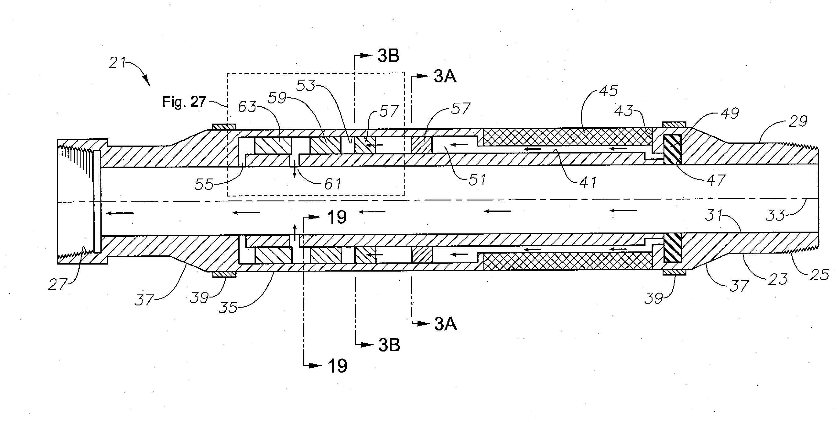
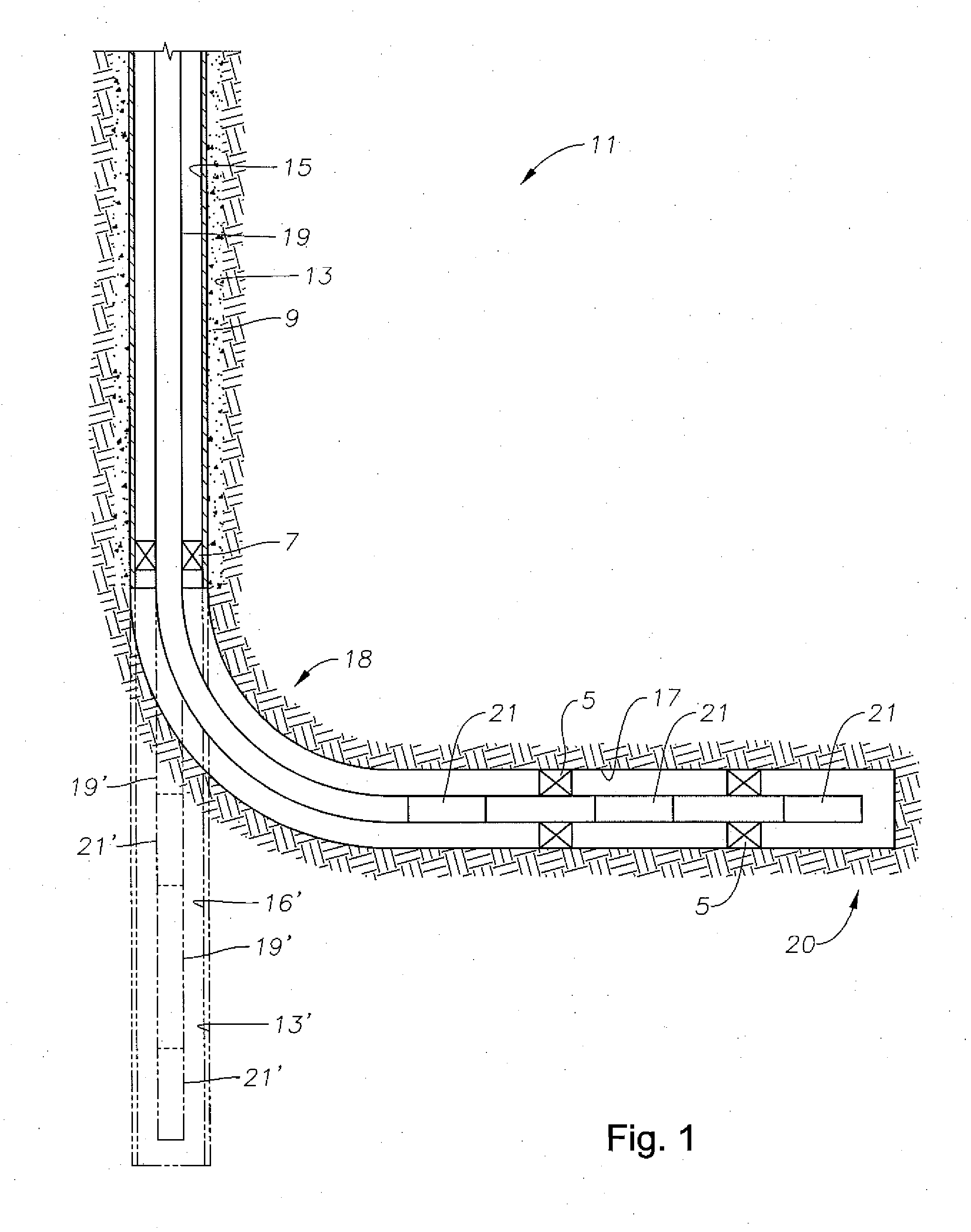
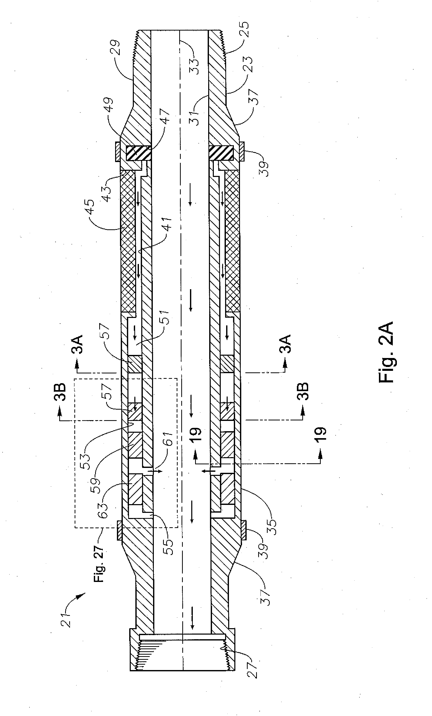
[0033]The present invention will now be described more fully hereinafter with reference to the accompanying drawings which illustrate embodiments of the invention. This invention may, however, be embodied in many different forms and should not be construed as limited to the illustrated embodiments set forth herein. Rather, these embodiments are provided so that this disclosure will be thorough and complete, and will fully convey the scope of the invention to those skilled in the art. Like numbers refer to like elements throughout, and the prime notation, if used, indicates similar elements in alternative embodiments or positions.

[0034]In the following discussion, numerous specific details are set forth to provide a thorough understanding of the present invention. However, it will be obvious to those skilled in the art that the present invention may be practiced without such specific details. Additionally, for the most part, details concerning well drilling, reservoir testing, well c...


PUM


Abstract

An inflow control device controls the rate of fluid flow from a subsurface fluid reservoir into a production tubing string. The inflow control device includes a particulate screen to remove particulate matter from the reservoir fluid, and at least two flow restrictors. The flow restrictors are positioned on circumferentially opposite sides of the inflow control device and are connected by an isolated fluid passage. The flow restrictors limit the flowrate of reservoir fluid when the reservoir fluid has a high water or gas-to-oil ratio. The inflow control device also includes at least one pressure drop device that generates a pressure drop for the reservoir fluid in response to fluid pressure in the reservoir. The inflow control device also includes a choking apparatus that allows the flow of reservoir fluid to be shut off and the particulate screen cleaned while the inflow control device is in place in hole.

Description

[0001]This application claims priority to and the benefit of co-pending U.S. Provisional Application No. 61 / 535,802, filed on Sep. 16, 2011, entitled “Self-Controlled Inflow Control Device,” which application is hereby incorporated herein by reference.BACKGROUND OF THE INVENTION[0002]1. Field of the Invention[0003]The present invention relates in general to well production devices and, in particular, to a self-controlled inflow control device.[0004]2. Brief Description of Related Art[0005]Some well completions use lateral lines to penetrate horizontally across a reservoir. These horizontal well sections extend through a reservoir at the same general elevation to produce fluid from across the reservoir rather than a localized area around a vertical well. The lateral lines extend from a heel at the junction of the lateral line with the vertical line to a toe at the end of the lateral line. Fluid along the horizontal wellbore profile will flow into the production tubing all along the l...

Claims


Application Information

Patent Timeline
IPC IPC(8): E21B34/06E21B43/00
CPCE21B34/08E21B43/14E21B43/12
Inventor ZHOU, SHAOHUA
Owner SAUDI ARABIAN OIL CO
Learn More