Reverse osmosis membrane separation device
a reverse osmosis membrane and separation device technology, applied in the direction of membranes, filtration separation, separation processes, etc., can solve the problems of membrane blockage, overconcentration, short supply volume to a demand position,
- Summary
- Abstract
- Description
- Claims
- Application Information
AI Technical Summary
Benefits of technology
Problems solved by technology
Method used
Image
Examples
first embodiment
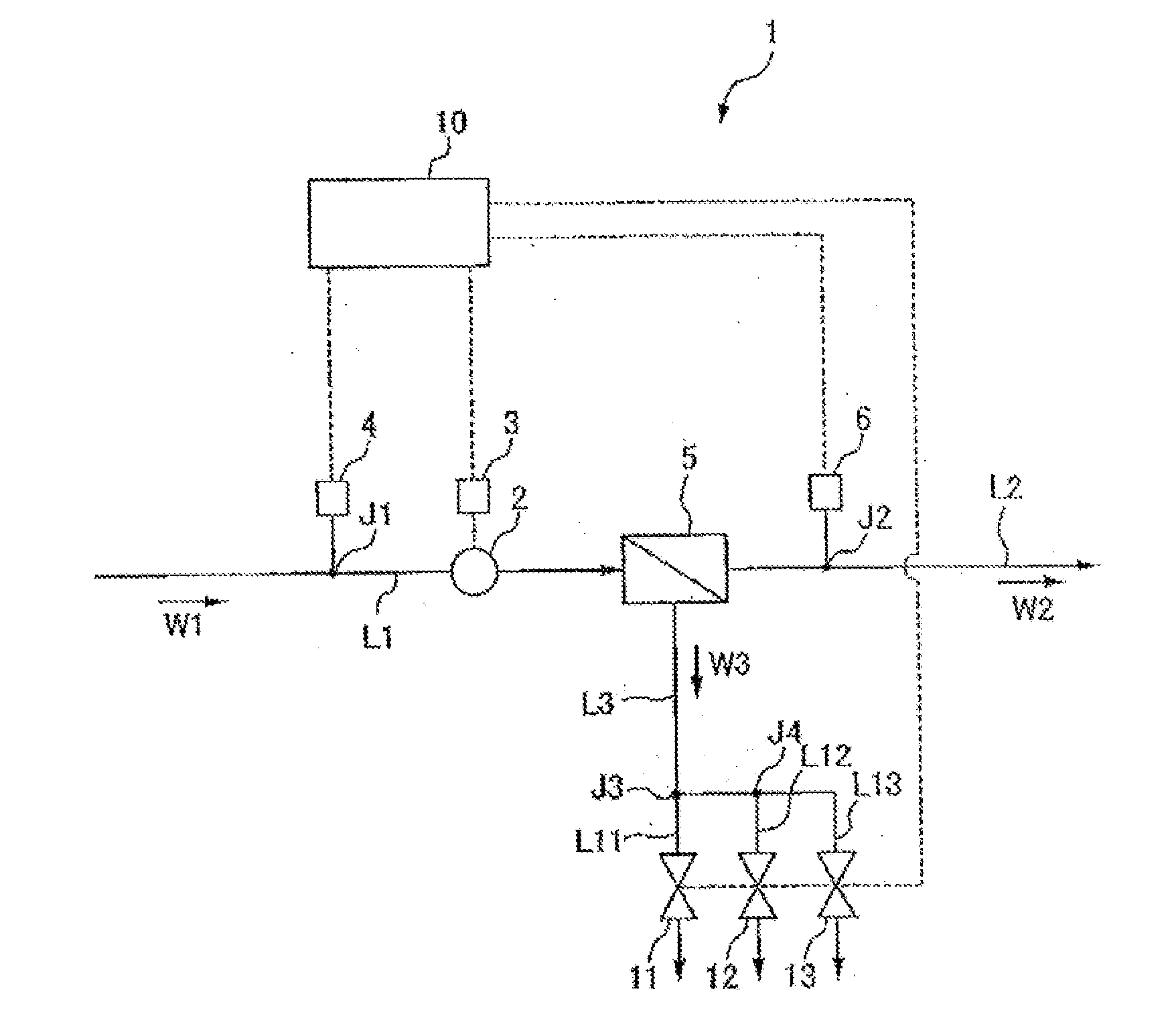
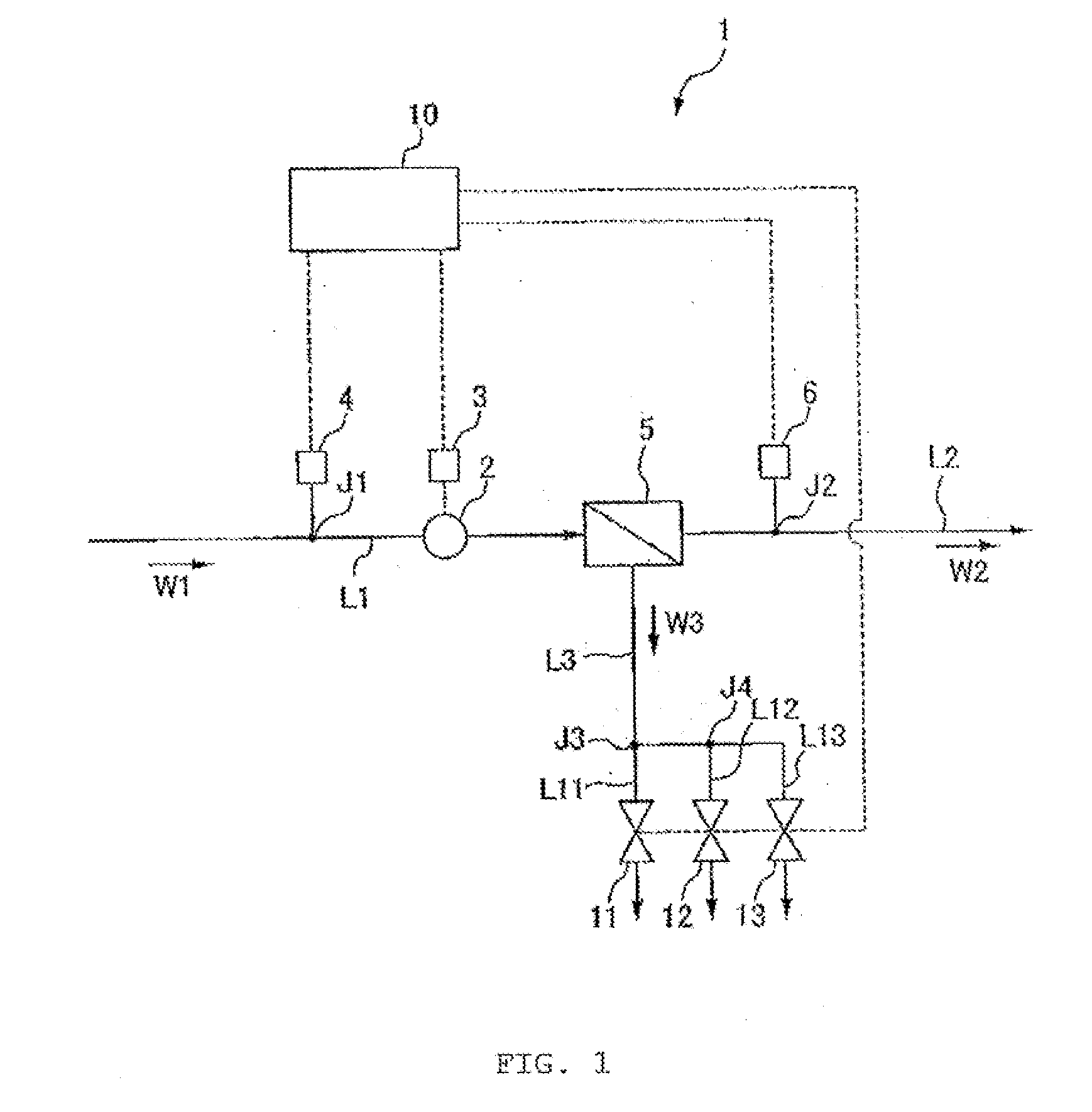
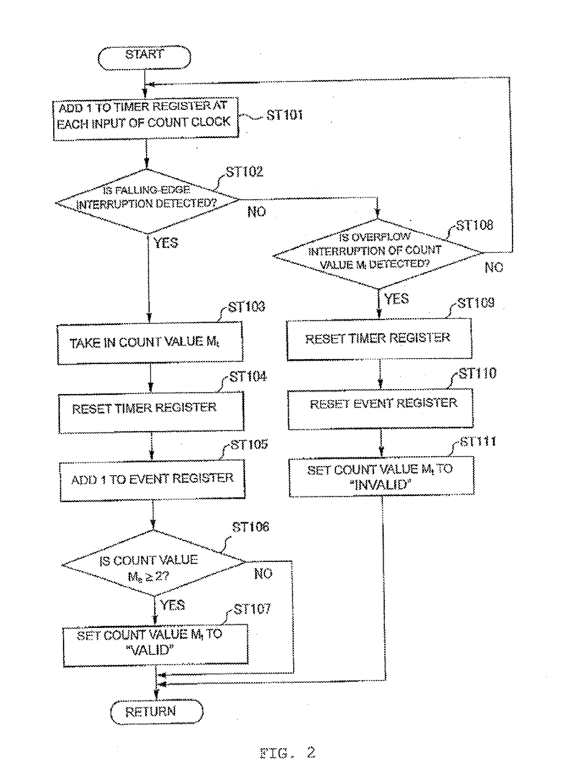
[0019]A reverse osmosis membrane separation device 1 according to a first embodiment of the present invention is described with reference to the drawings. An object of the first embodiment is to provide a reverse osmosis membrane separation device 1 that can keep a flow rate of permeate water at a target flow rate value, even when a water permeability coefficient of an RO membrane module rapidly changes. The reverse osmosis membrane separation device 1 according to the first embodiment is applied to a pure water production system that produces pure water from fresh water, for example. FIG. 1 is an overall configuration diagram of the reverse osmosis membrane separation device 1 according to the first embodiment. FIG. 2 is a flowchart showing a processing procedure employed when a control unit 10 calculates a time width, of a flow rate pulse signal. FIG. 3 is a flowchart showing a processing procedure employed when the control unit 10 calculates a detected flow rate value as numerica...
second embodiment
[0091]A configuration of a reverse osmosis membrane separation device 1A according to a second embodiment of the present invention is described next with reference to FIG. 6. FIG. 6 is an overall configuration diagram of the reverse osmosis membrane separation device 1A according to the second embodiment. In the second embodiment, differences from the first embodiment are mainly described. In a description of the second embodiment, configurations that are the same as or equivalent to those in the first embodiment are assigned with the same reference numerals or symbols. In the second embodiment, a description redundant with that of the first embodiment is suitably omitted.
[0092]As shown in FIG. 6, the reverse osmosis membrane separation device 1A according to the second embodiment includes the pressure pump 2, the inverter equipment 3, the RO membrane module 5, the flow rate sensor 6, a hardness sensor 7 as a hardness measuring unit, a control unit 10A, and the first drain valve 11 ...
third embodiment
[0105]A configuration of a reverse osmosis membrane separation device 1B according to a third embodiment of the present invention is described next with reference to FIG. 8. FIG. 8 is an overall configuration diagram of the reverse osmosis membrane separation device 1B according to the third embodiment. In the third embodiment, differences from the first embodiment are mainly described. In a description of the third embodiment, configurations that are the same as or equivalent to those in the first embodiment are assigned with the same reference numerals or symbols. In the third embodiment, a description redundant with that of the first embodiment is suitably omitted.
[0106]As shown in FIG. 3, the reverse osmosis membrane separation device 1B according to the third embodiment includes the pressure pump 2, the inverter equipment 3, the RO membrane module 5, the flow rate sensor 6, an electric conductivity sensor 8 as an electric conductivity measuring unit, a control unit 10B, and the...
PUM
| Property | Measurement | Unit |
|---|---|---|
| Electrical conductivity | aaaaa | aaaaa |
Abstract
Description
Claims
Application Information
 - R&D
- Intellectual Property
- Life Sciences
- Materials
- Tech Scout
- Unparalleled Data Quality
- Higher Quality Content
- 60% Fewer Hallucinations
Browse by: Latest US Patents, China's latest patents, Technical Efficacy Thesaurus, Application Domain, Technology Topic, Popular Technical Reports.
© 2025 PatSnap. All rights reserved.Legal|Privacy policy|Modern Slavery Act Transparency Statement|Sitemap|About US| Contact US: help@patsnap.com


