Ion sensor, display device, method for driving ion sensor, and method for calculating ion concentration

a technology of ion sensor and display device, which is applied in the direction of measurement device, semiconductor device, instrument, etc., can solve the problem of inability to check the generation of ions by direct eye observation, and achieve the effect of high accuracy

Inactive Publication Date: 2013-03-21
SHARP KK
View PDF2 Cites 8 Cited by
  • Summary
  • Abstract
  • Description
  • Claims
  • Application Information

AI Technical Summary

Benefits of technology

[0091]According to the present invention, it is possible to provide an ion sensor that can measure with high accuracy an ion concentration in a sample in which both ions are mixed, a display device, a method for driving the ion sensor, and a method for calculating an ion concentration.

Problems solved by technology

Since ions are invisible, checking generation of ions by direct eye-observation is not possible.

Method used


Image

  • Ion sensor, display device, method for driving ion sensor, and method for calculating ion concentration
  • Ion sensor, display device, method for driving ion sensor, and method for calculating ion concentration
  • Ion sensor, display device, method for driving ion sensor, and method for calculating ion concentration

Examples


embodiment 1

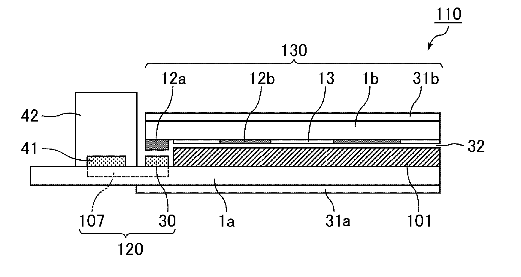
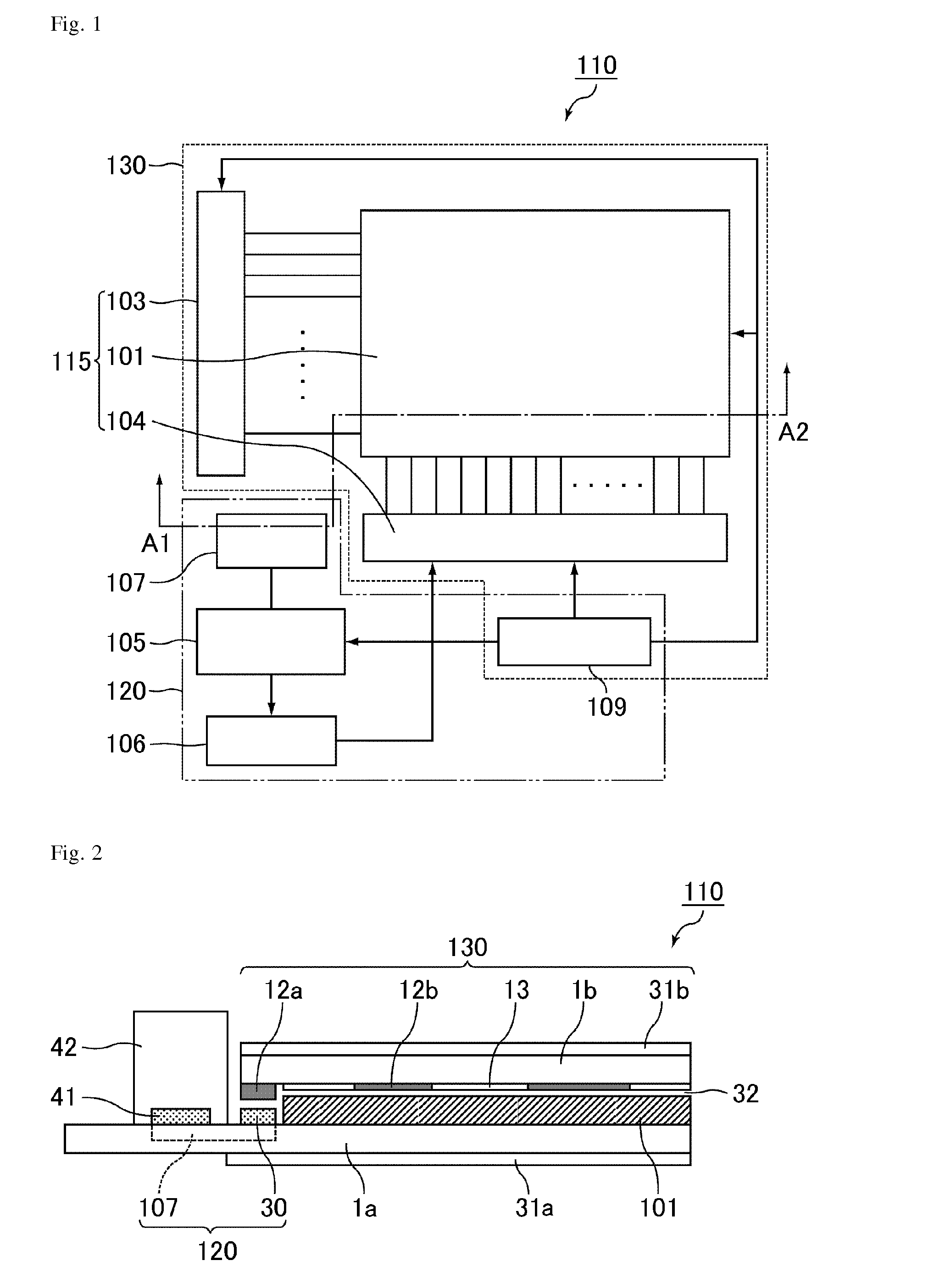
[0119]The present embodiment is described based on examples of an ion sensor including N-channel TFTs and configured to detect ions in the air, and a liquid crystal display device including the ion sensor. FIG. 1 is a block diagram of an ion sensor and a display device according to the present embodiment.

[0120]A display device 110 according to the present embodiment is a liquid crystal display device, and includes an ion sensor 120 (ion sensor portion) for measuring the ion concentration in the air, and a display 130 for displaying various images. The display 130 is provided with a display-driving circuit 115 that includes a display-driving TFT array 101, a gate driver (scanning signal line-driving circuit for display) 103, and a source driver (image signal line-driving circuit for display) 104. The ion sensor 120 includes an ion sensor driving / reading circuit 105, an arithmetic processing LSI 106, and an ion sensor circuit 107. A power supply circuit 109 is shared by the ion sensor...

embodiment 2

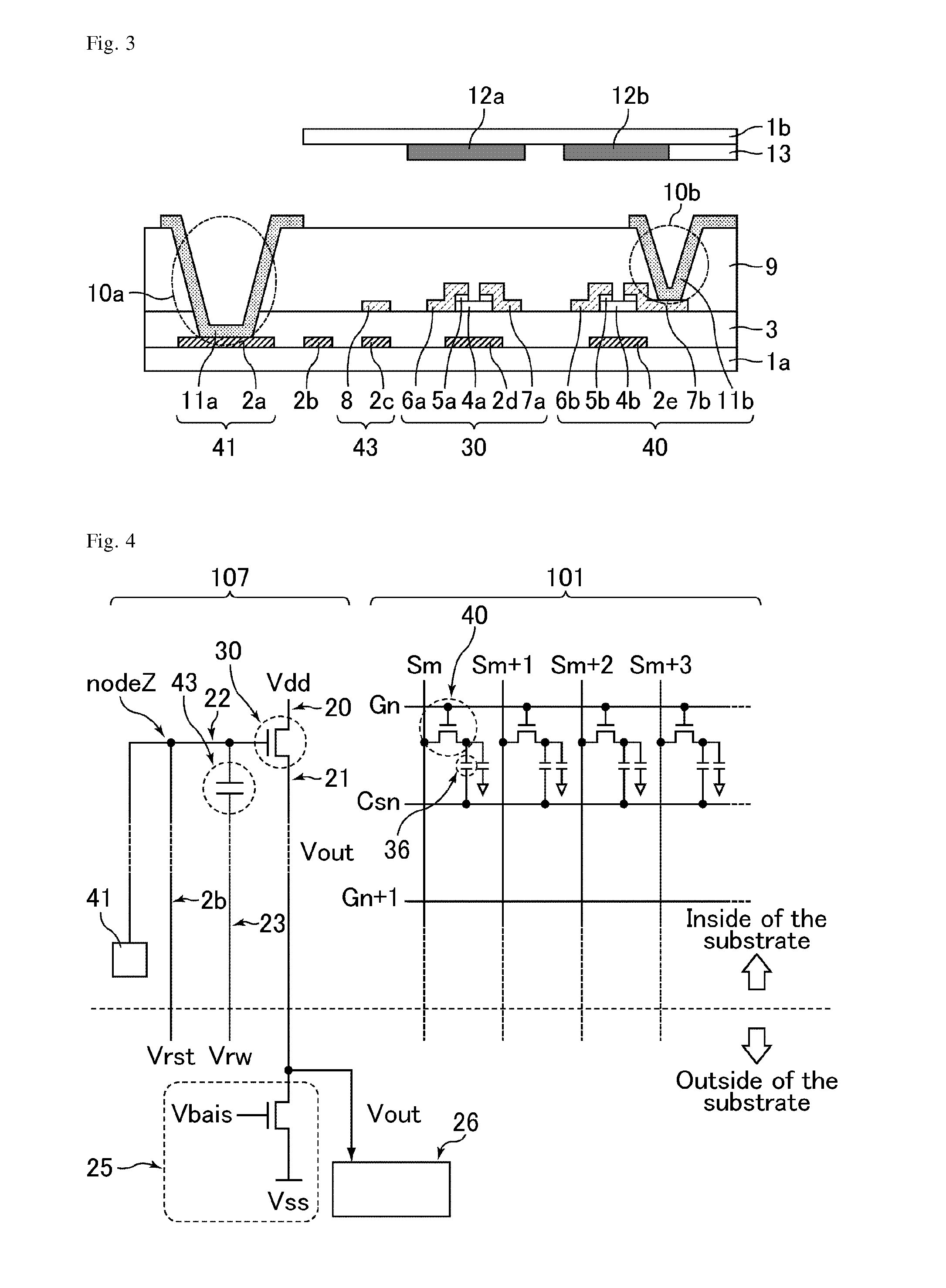
[0157]A display device according to Embodiment 2 has the same configuration as Embodiment 1, except for the following points. That is, an ion sensor circuit 207 of Embodiment 2 includes a negative ion-detecting sensor circuit 201 and a positive ion-detecting sensor circuit 202. The negative ion-detecting sensor circuit 201 includes the N-channel sensor TFT 30 and the antenna 41 described in Embodiment 1. The positive ion-detecting sensor circuit 202 includes a P-channel sensor TFT 30b and an antenna 41b.

[0158]The configuration of the positive ion-detecting sensor circuit 202 will now be described in detail using FIG. 6. FIG. 6 is a schematic cross-sectional view of the ion sensor and the display device according to the present embodiment, and includes one portion of the positive ion-detecting sensor circuit. A description of common components with respect to the display device according to Embodiment 1 is omitted here.

[0159]As shown in FIG. 6, the sensor circuit 202 is an ion senso...

embodiment 3

[0184]A display device according to Embodiment 3 has the same configuration as that of Embodiment 2 except for the following points. That is, an ion sensor circuit 307 of Embodiment 3 includes a negative ion-detecting sensor circuit 301 and a positive ion-detecting sensor circuit 302, and the sensor circuits 301 and 302 each include a push-up / push-down line. The sensor circuit 302 includes an N-channel sensor TFT 30c instead of the P-channel sensor TFT 30b.

[0185]The circuit configuration of the ion sensor circuit 307 according to the present embodiment will now be described using FIG. 10. FIG. 10 is an equivalent circuit that illustrates the ion sensor circuit 307 and one part of the TFT array 101 according to the present embodiment. The display device according to the present embodiment has the same TFT array 101 as Embodiment 1, and hence a description thereof is omitted here.

[0186]The ion sensor circuit 307 includes the negative ion-detecting sensor circuit 301 and the positive ...


PUM


Abstract

The present invention provides an ion sensor with which an ion concentration in a sample in which both ions are mixed can be measured with high accuracy, a display device, a method for driving the ion sensor, and a method for calculating an ion concentration. The present invention is an ion sensor that includes a field effect transistor. The ion sensor detects one of negative ions and positive ions using the field effect transistor, and consecutively thereafter detects the other of the negative ions and positive ions using the field effect transistor.

Description

TECHNICAL FIELD[0001]The present invention relates to an ion sensor, a display device, a method for driving an ion sensor, and a method for calculating an ion concentration. More specifically, the present invention relates to an ion sensor that is suitable as an ion sensor that includes a field effect transistor (hereinafter, also referred to as “FET”), a display device that includes the ion sensor, a method for driving the ion sensor, and a method for calculating an ion concentration that uses the ion sensor.BACKGROUND ART[0002]A technology of generating positive ions and negative ions (hereinafter, also referred to as “both ions” or simply as “ions”) in the air has recently been found to have an effect of killing bacteria floating in the air and purify the air. An ion generator employing the technology, such as an air purifier, has matched the comfort and the recent trends towards health-conscious lifestyle, and thus has drawn much attention.[0003]Since ions are invisible, checkin...

Claims


Application Information

Patent Timeline
Patent Type & Authority Applications(United States)
IPC IPC(8): H01L29/772
CPCG01N27/4148
Inventor MURAI, ATSUHITOKATAOKA, YOSHIHARUWATANABE, TAKUYAHISADA, YUHKOHORIUCHI, SATOSHI
Owner SHARP KK
Why Eureka
Try Eureka