Electrical monitoring device and method for safeguarding the protective function of a type a residual current device (RCD)

a residual current and monitoring device technology, applied in emergency protective arrangements for limiting excess voltage/current, power supply testing, instruments, etc., can solve the problems of only operative protection effect of type a residual current devices, different current, and release of such devices, so as to improve electrical protection

a residual current and monitoring device technology, applied in emergency protective arrangements for limiting excess voltage/current, power supply testing, instruments, etc., can solve the problems of only operative protection effect of type a residual current devices, different current, and release of such devices, so as to improve electrical protection

US20130070374A1Active Publication Date: 2013-03-21BENDER SA

Image

  • Electrical monitoring device and method for safeguarding the protective function of a type a residual current device (RCD)
  • Electrical monitoring device and method for safeguarding the protective function of a type a residual current device (RCD)

Examples


Embodiment Construction

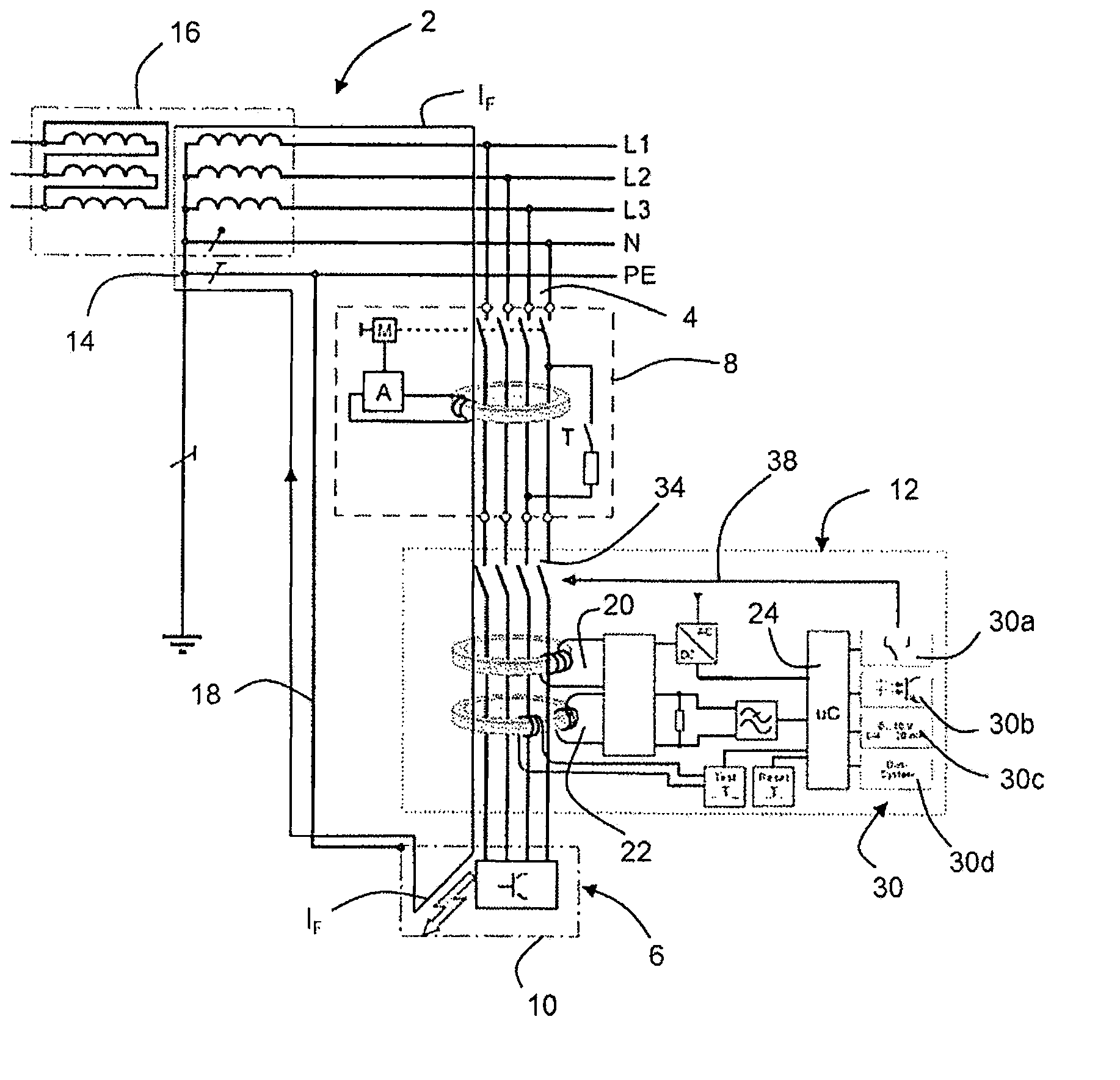
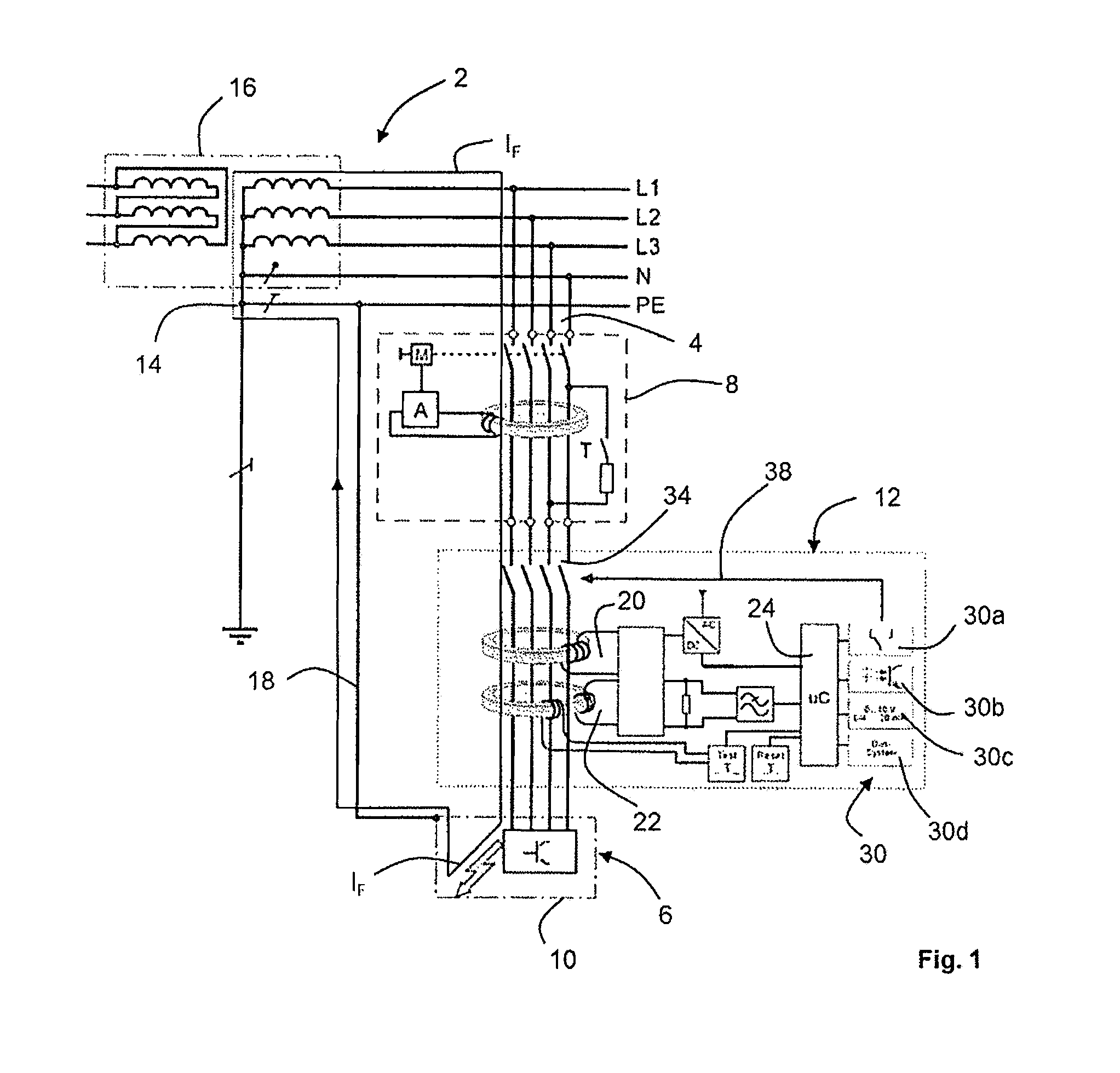
[0039]FIG. 1 shows an electricity supply system 2 designed as a TN system 2, to which an operating component (consumer) 6 is connected via a feed line (outgoing power feed) 4. A type A residual current device (RCD) 8 is arranged in outgoing power feed 4 to provide protection in the event that bodies 10 of electrical operating components 6 come into contact. In order to safeguard the function of type A residual current device (RCD) 8, a monitoring device 12 according to the invention in the variant with two measuring current transformer circuits (20, 22) is connected in series. TN system 2 includes three outer conductors L1, L2 and L3 besides the neutral conductor N and the protective ground PE. A point 14 at power feed 16 is grounded directly, body 10 of operating component 6 is connected to this grounding point 14 via a protective ground connection 18.

[0040]The inventive monitoring device 12 has two measuring current transformer circuits 20, 22, of which first measuring current tra...


PUM


Abstract

A monitoring device and a method safeguards the function of a type A residual current device (RCD) in a power supply system. The monitoring device includes a measuring current transformer circuit for detecting a DC fault current (IF), an evaluation unit for processing the current detected by the measuring current transformer circuit, and a communication interface connected to the output of evaluation unit. In one embodiment, the monitoring device forms part of an electrical protection device with a type A residual current device (RCD) for ensuring the function of the type A residual current device (RCD).

Description

CROSS REFERENCE TO RELATED APPLICATION[0001]The present application claims the benefit of German Patent Application No. 10 2011 082 941.5 filed Sep. 19, 2011, which is fully incorporated herein by reference.STATEMENT REGARDING FEDERALLY SPONSORED RESEARCH OR DEVELOPMENT[0002]Not applicable.FIELD OF THE INVENTION[0003]The invention relates to a monitoring device and a method for safeguarding the function of a type A residual current device (RCD) in a power supply system.[0004]The invention further relates to an electrical protection device with a type A residual current device (RCD) and with a monitoring device according to the invention for ensuring the function of the type A residual current device (RCD).BACKGROUND OF THE INVENTION[0005]Residual current devices (RCD) are known to serve as protective means in electrical systems in the event of contact between the bodies of electrical operating materials, and they are provided to offer protection in special areas of electrical system...

Claims


Application Information

Patent Timeline
21 Mar 2013
Publication
US20130070374A1
IPC
H02H3/16; G06F19/00; G01R31/40
CPC
H02H3/332; H02H5/12
Inventors
HOFHEINZ, WOLFGANG; SELLNER, HARALD