Microrobot system for intravascular therapy and method of controlling the same

a technology of microrobots and intravascular therapy, which is applied in the field of microrobot systems for intravascular therapy, can solve the problems of high power consumption and difficulty in directly applying to patients, and achieve the effect of reducing power consumption, reducing thrombosis, and reducing thrombosis

Active Publication Date: 2013-03-21
IND FOUND OF CHONNAM NAT UNIV
View PDF9 Cites 8 Cited by
  • Summary
  • Abstract
  • Description
  • Claims
  • Application Information

AI Technical Summary

Benefits of technology

[0010]According to the present invention, an electromagnetic field generation unit (a coil system) has the shape of a horizontally arranged cylinder, thus simplifying a working space and performing the same function as that of a conventional coil system that is vertically arranged.
[0011]Further, a microrobot is formed in a spherical shape, so that drilling and propulsion can be driven together without requiring the rotation of coil units, thus easily removing thrombus, clots and occlusions accumulated in blood vessels.

Problems solved by technology

However, these technologies are problematic in that the number of coils is large to cause in high power consumption and in that a coil system has the structure of a working space making it difficult to be directly applied to patients.

Method used


Image

  • Microrobot system for intravascular therapy and method of controlling the same
  • Microrobot system for intravascular therapy and method of controlling the same
  • Microrobot system for intravascular therapy and method of controlling the same

Examples


Embodiment Construction

[0019]The above and other objects, features and advantages of the present invention will be more clearly understood from the following detailed description taken in conjunction with the accompanying drawings. Further, if in the specification, detailed descriptions of well-known functions or configurations may unnecessarily make the gist of the present invention obscure, the detailed descriptions will be omitted.

[0020]Hereinafter, embodiments of the present invention will be described in detail with reference to the attached drawings.

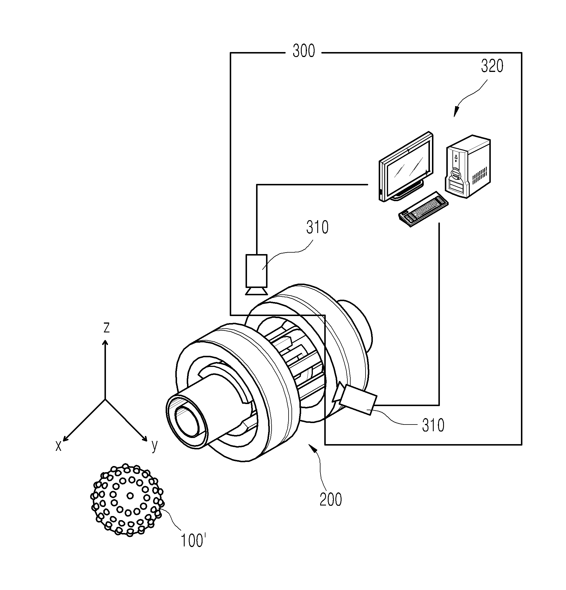
[0021]The present invention relates to a microrobot system for intravascular therapy and a method of controlling the microrobot system, and will be described with reference to FIGS. 1 to 7.

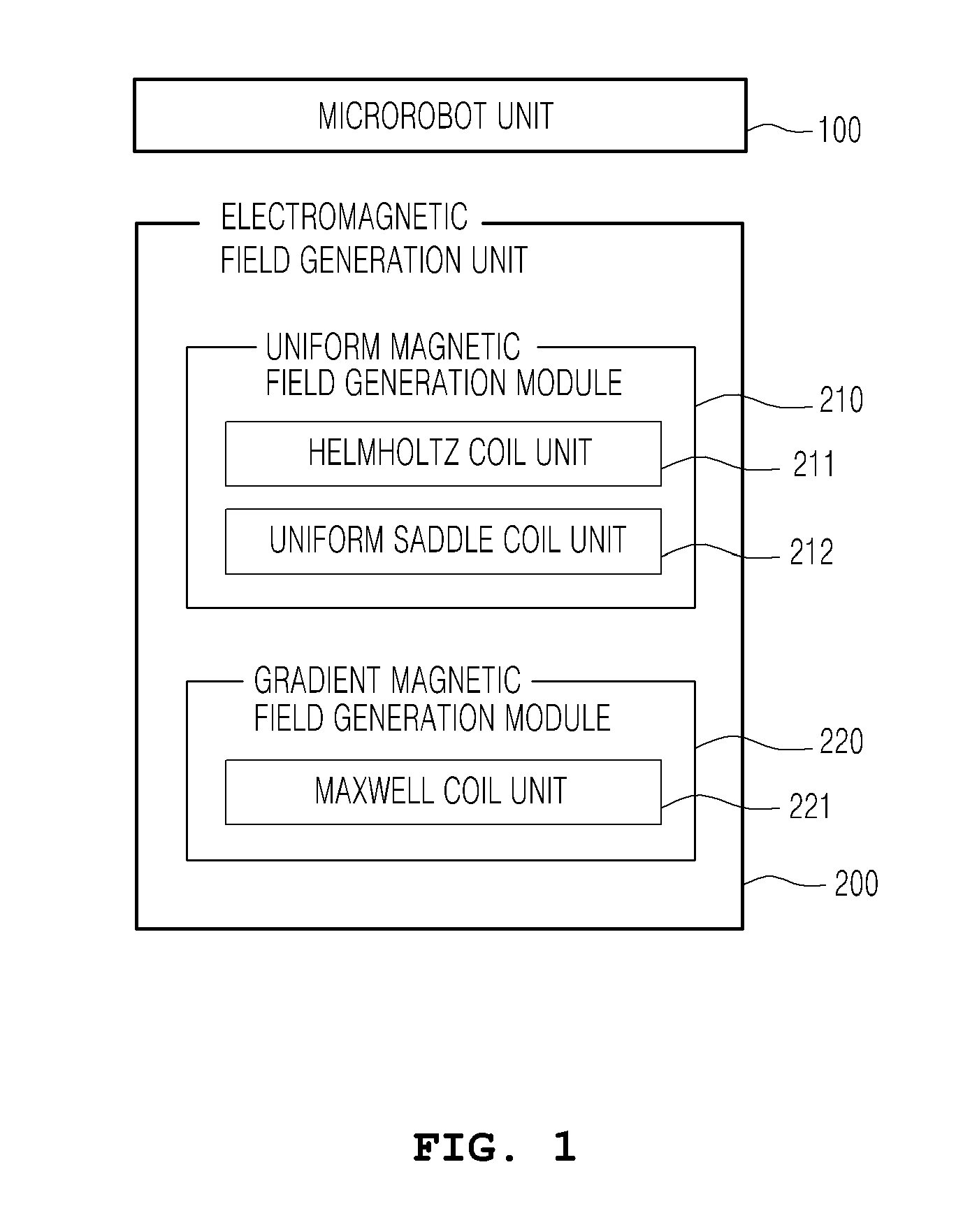
[0022]FIG. 1 is a block diagram showing a microrobot system according to an embodiment of the present invention, and the microrobot system includes a microrobot unit 100 and an electromagnetic field generation unit 200.

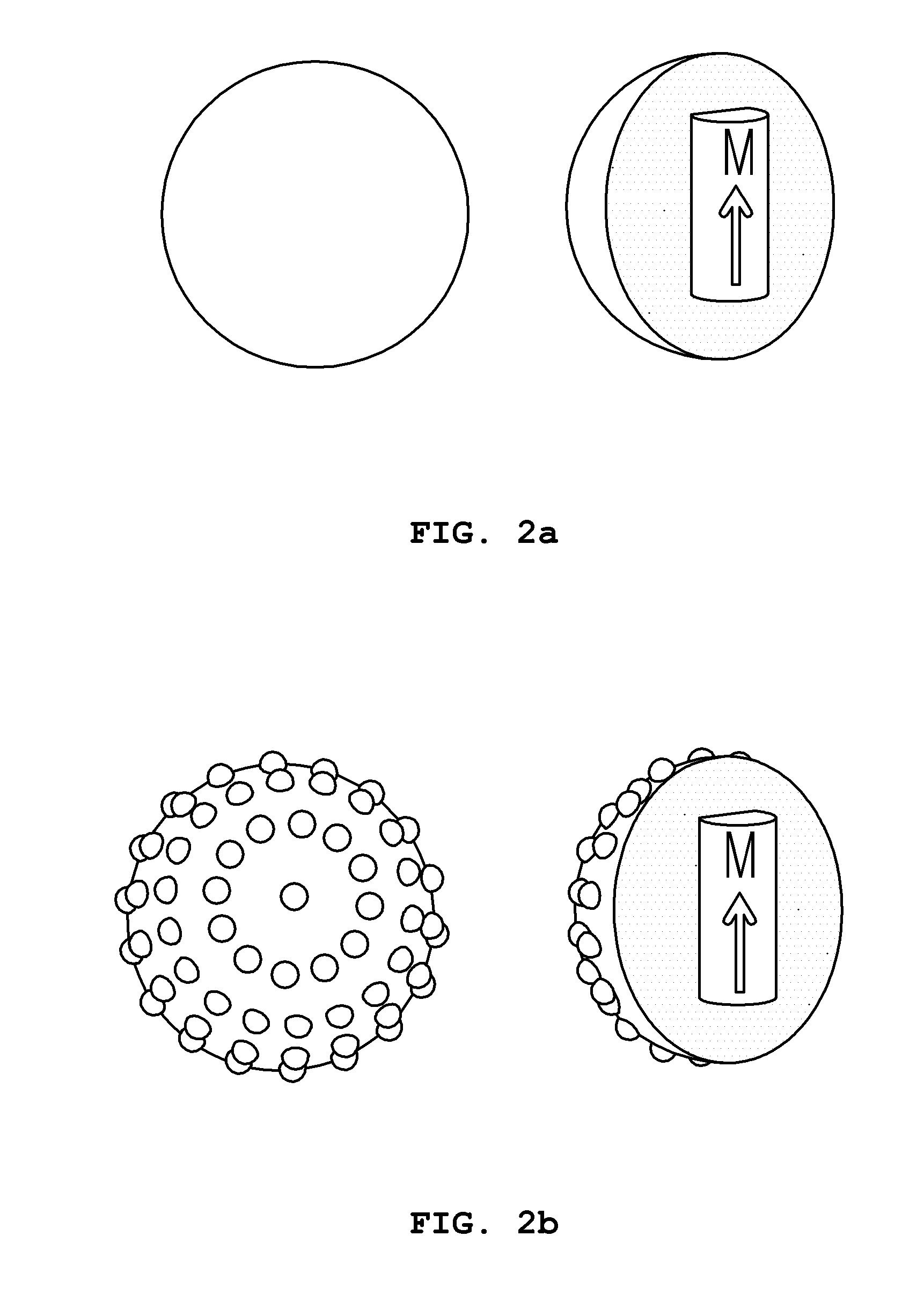
[0023]The microrobot unit 100 includes a spherical...


PUM

PropertyMeasurementUnit
magnetizationaaaaaaaaaa
magnetic fieldsaaaaaaaaaa
electromagnetic fieldaaaaaaaaaa

Abstract

The present invention relates, in general, to a microrobot system for intravascular therapy and, more particularly, to a microrobot system for intravascular therapy, which removes thrombus, clots and occlusions that are clogging blood vessels using the fast rotary power of a spherical microrobot having protrusions, thus treating clogged blood vessels.
The microrobot system for intravascular therapy according to the present invention includes a spherical microrobot unit (100′) including a magnet having an arbitrary magnetization direction and having protrusions formed on a surface thereof. An electromagnetic field generation unit (200) sets an alignment direction and a locomotion direction of the microrobot unit to arbitrary directions in the 3D space, generates magnetic fields, and then drives the microrobot unit so that the microrobot unit is rotated by itself or is propelled in the locomotion direction. An imaging unit (300) captures an X-ray image and then tracking a location of the microrobot unit.

Description

TECHNICAL FIELD[0001]The present invention relates, in general, to a microrobot system for intravascular therapy and, more particularly, to a microrobot system for intravascular therapy, which removes thrombus, clots and occlusions that are clogging blood vessels using the fast rotary power of a spherical microrobot having protrusions, thus treating clogged blood vessels.BACKGROUND ART[0002]Minimally invasive surgery using a microrobot is surgery enabling an incised part to be minimized, the pain of a patient to be reduced, and the recuperation period to be shortened, and a lot of research has been conducted into such minimally invasive surgery. In particular, research into technology for propelling a microrobot or driving the microrobot to administer medical treatment using external magnetic fields has been widely conducted. Most research has been mainly conducted based on a two-dimensional (2D) plane or simple movement performed in a three-dimensional (3D) space.[0003]Korean Paten...

Claims


Application Information

Patent Timeline
Patent Type & Authority Applications(United States)
IPC IPC(8): H01F7/02A61B6/12
CPCH01F7/02A61B6/12A61B19/2203A61N2/002A61B2019/2249A61B2019/2253A61B2019/5238A61B2019/2219A61B2017/00345A61B34/30A61B34/72A61B34/73A61B2034/303A61B2090/376A61B18/00A61N2/02A61N2/06
Inventor PARK, SUK HOPARK, JONG OHCHOI, HYUN CHULCHA, KYOUNG RAEJEONG, SE MI
Owner IND FOUND OF CHONNAM NAT UNIV
Why Eureka
Try Eureka