Monitoring method and monitor apparatus for monitoring rotation speed of rotary shaft in machine tool, and machine tool

Active Publication Date: 2013-03-21
OKUMA CORP
View PDF3 Cites 7 Cited by
  • Summary
  • Abstract
  • Description
  • Claims
  • Application Information

AI Technical Summary

Benefits of technology

[0006]The present invention was devised to solve the foregoing problems, and it is an object of the present invention to provide a monitoring method and a monitor apparatus for monitoring a rotation speed of a rotary shaft in a machine

Problems solved by technology

When machining a workpiece with low rigidity using a machine tool or during machining that uses a tool with low rigidity, sharp vibration known as chatter vibration often occurs during cutting.
Chatter vibration produces a cyclical pattern generally known as a chatter mark on the machined surface, and causes degradation of the finished surface texture and machining accuracy, Cyclic fluctuations in cutting force cause noise, which may lead to problems such as tool wear and loss.
In the pas

Method used


Image

  • Monitoring method and monitor apparatus for monitoring rotation speed of rotary shaft in machine tool, and machine tool
  • Monitoring method and monitor apparatus for monitoring rotation speed of rotary shaft in machine tool, and machine tool
  • Monitoring method and monitor apparatus for monitoring rotation speed of rotary shaft in machine tool, and machine tool

Examples


Embodiment Construction

[0033]Hereinafter, an embodiment of the present invention will be described on the basis of the drawings.

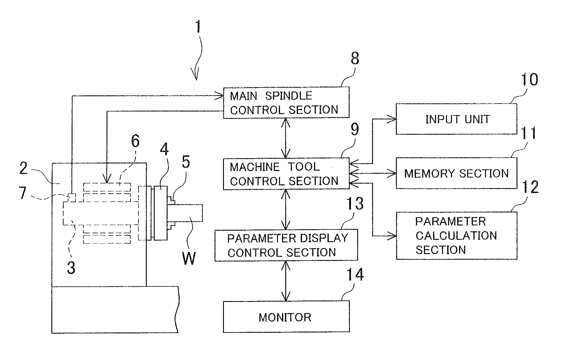
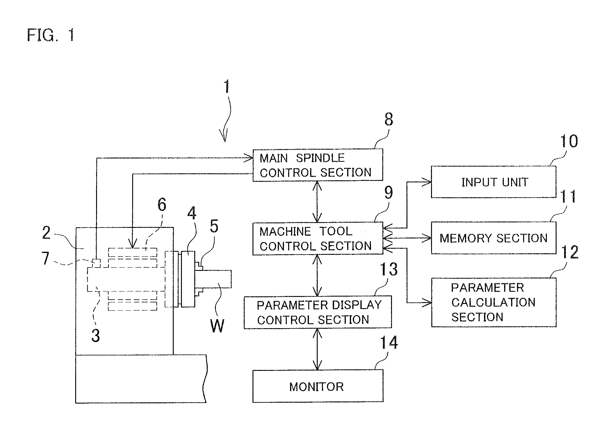
[0034]FIG. 1 is a schematic configuration diagram of an NC lathe 1 that is an example of a machine tool. In the NC lathe 1, a headstock 2 rotatably supports a main spindle 3. The main spindle 3 serves as a rotary shaft that holds a workpiece W through a chuck 4 and claws 5. A motor 6 that rotatingly drives the main spindle 3, and an encoder 7 that is fixed to the headstock 2 and detects a rotation speed of the main spindle 3 are built into the headstock 2.

[0035]Reference numeral 8 denotes a main spindle control section that is connected to the motor 6 and the encoder 7. Reference numeral 9 denotes a machine tool control section that instructs a rotation speed to the main spindle control section 8. The main spindle control section 8 constantly monitors the detected rotation speed of the main spindle 3 from the encoder 7, and also adjusts the power supplied to the motor 6 such that...


PUM


Abstract

When a rotation speed is fluctuated, a fluctuation diagram showing the relationship between a fluctuation amplitude and a fluctuation period of the rotation speed is displayed on a monitor. In addition to a current setting value, a settable range of the fluctuation amplitude and the fluctuation period is displayed on the fluctuation diagram. At least one of an optimal fluctuation period PO based on Equation (1) below and an optimal range P1 of the fluctuation period based on Equation (2) below is also displayed on the fluctuation diagram, wherein T is a rotation period of a rotary shaft, and a, amin, amax are preset coefficients.
PO=aT  (1)
aminT≦P1≦amaxT  (2)

Description

BACKGROUND OF INVENTION[0001]This application claims the benefit of Japanese Patent Application Number 2011-204676 filed on Sep. 20, 2011, the entirety of which is incorporated by reference.TECHNICAL FIELD[0002]The present invention relates to a monitoring method and a monitor apparatus for monitoring, in a machine tool including a rotary shaft that is mounted with a tool or a workpiece and driven by a motor, and a rotation speed fluctuating unit that continuously fluctuates a rotation speed of the rotary shaft at an arbitrary pattern, a fluctuating condition of the rotation speed caused by the rotation speed fluctuating unit on a display section, and also relates to a machine tool equipped with the monitor apparatus.BACKGROUND ART[0003]When machining a workpiece with low rigidity using a machine tool or during machining that uses a tool with low rigidity, sharp vibration known as chatter vibration often occurs during cutting. Chatter vibration produces a cyclical pattern generally ...

Claims


Application Information

Patent Timeline
IPC IPC(8): G06F15/00G01P3/00
CPCG05B2219/41256G05B19/4062
Inventor NISHIMURA, KOHEIYOSHINO, KIYOSHIISHII, HAJIMU
Owner OKUMA CORP
Why Eureka
Try Eureka