
Bicycle with suspension

a technology for suspension systems and bicycles, applied in the direction of shock absorbers, cycle springs, steering devices, etc., can solve the problems of increased shock absorption, increased shock absorption, and increased shock absorption, so as to reduce the pressure within the shock absorber, reduce the effect of pressure and pressure reduction

Active Publication Date: 2013-03-28
SPECIALIZED BICYCLE COMPONENTS INC
View PDF7 Cites 9 Cited by
  • Summary
  • Abstract
  • Description
  • Claims
  • Application Information

AI Technical Summary

Benefits of technology

The patent describes a shock used in bicycles that can adjust the air pressure to improve performance. The shock includes a main air chamber, a secondary air chamber, a valve, and an outer valve housing. The valve can be opened or closed to control the air pressure in the main chamber and the secondary chamber. The shock can also have a control member that can adjust the pressure in the main chamber by venting the secondary chamber to the atmosphere. The technical effects of this invention include improved shock absorption, reduced weight, and improved performance.

Problems solved by technology

However, because mountain bikes are typically pedal-driven, i.e., use the rider's power output to propel the bicycle, the provision of rear suspension, especially, may undesirably absorb a rider's power output, resulting in wasted effort.
Accordingly, rear suspension systems commonly incorporated on engine-driven vehicles, such as motorcycles, have proven undesirable for use with pedal-driven vehicles, such as mountain bikes.
Rear suspension systems of engine-driven vehicles commonly emphasize strength over weight and, therefore, have not been widely incorporated on mountain bikes.
All of these different adjustments can be overwhelming to a user, especially a less experienced rider.
Not only do some shock absorbers have multiple adjustments but some adjustments require a specific procedure that can be time consuming and difficult to perform.
This can further complicate the procedure.
Because of the perceived difficulty of certain, if not all of the adjustments, some riders may have the shock absorber adjusted or set-up when it is originally purchased and then make no further adjustments.
In addition, certain bike shops or consumers may not make all of the right adjustments.

Method used


Image

  • Bicycle with suspension
  • Bicycle with suspension
  • Bicycle with suspension

Examples


Embodiment Construction

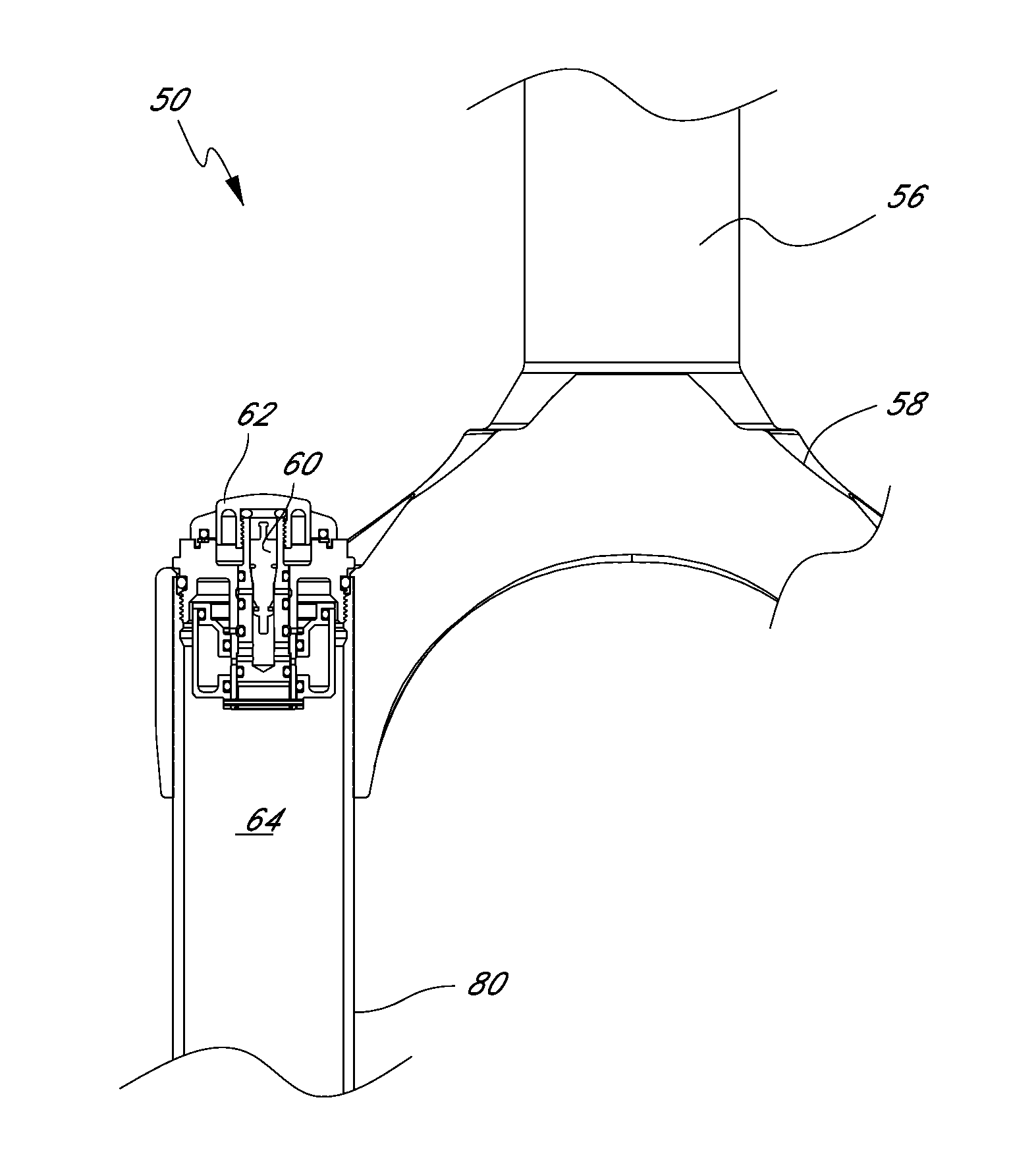
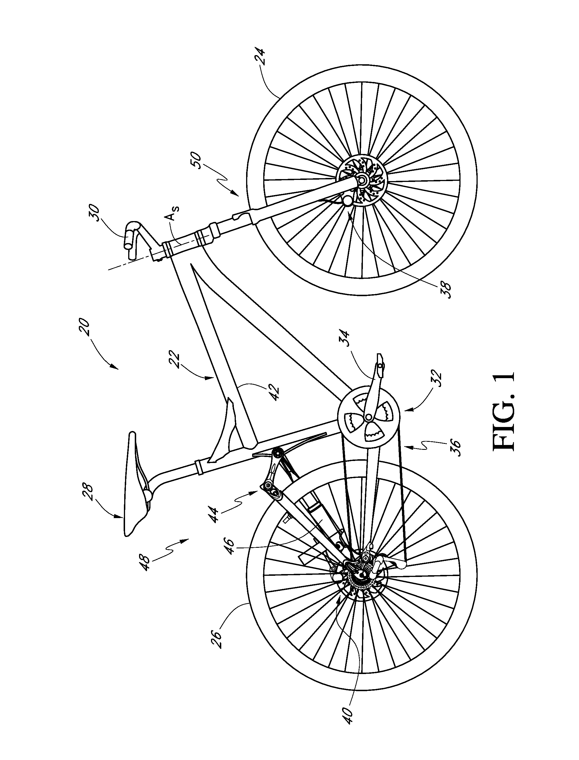
[0031]FIG. 1 illustrates a bicycle, and more particularly, an off-road bicycle or mountain bike 20. To aid in the description of the mountain bike 20 and the present suspension assembly, certain directional or relative terms may be used herein. The term “longitudinal” refers to a direction, length or a location between the front and rear of the bicycle 20. The term “lateral” refers to a direction, length or location between the sides of the bicycle 20. Heights may be described as relative distances from a surface upon which the bicycle 20 is operated in a normal manner. Thus, the terms “above” or “below” generally apply to the bicycle as assembled, and being oriented as it would be normally ridden, or as it is depicted in any of the relevant figures. Front, rear, left, and right directions generally refer to those directions from the perspective of a rider normally seated on the bicycle 20.

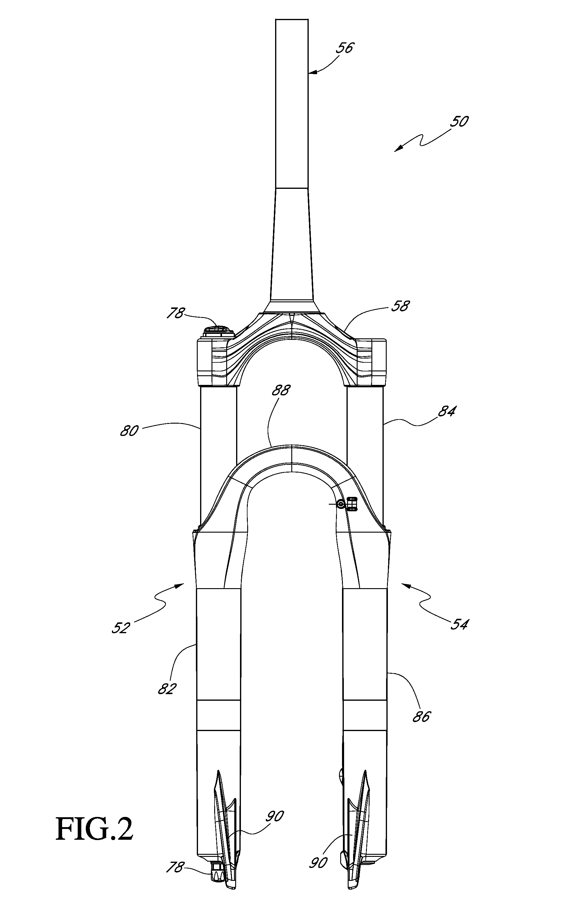
[0032]With reference to FIG. 1, the mountain bike 20 includes a frame assembly 22, a front whe...


PUM


Abstract

A bicycle assembly can include a front or rear suspension system with a shock absorber. A front suspension system can be a suspension fork. A rear suspension system can include a rear shock absorber. The shock can have a shock body and a pressurized main air chamber within the shock body to act as an air spring. The shock can also have a valve configured to receive a pump for adding air to the main air chamber. A secondary air chamber and a control member can be used to reduce the pressure within the main air chamber by venting the secondary air chamber to the atmosphere.

Description

CROSS-REFERENCE TO RELATED APPLICATIONS[0001]N / ABACKGROUND OF THE INVENTION[0002]1. Field of the Invention[0003]The present invention relates generally to bicycle suspension systems. In particular, the present invention relates to shock absorbers and suspension assemblies suitable for use in connection with off-road bicycles.[0004]2. Description of the Related Art[0005]Off-road bicycles, or mountain bikes, may be equipped with front and rear suspension assemblies operably positioned between the frame of the bicycle and the front and rear wheels, respectively. Providing front and rear suspension on a mountain bike potentially improves handling and performance by absorbing bumps, and other rough trail conditions, which may be encountered while riding off-road. However, because mountain bikes are typically pedal-driven, i.e., use the rider's power output to propel the bicycle, the provision of rear suspension, especially, may undesirably absorb a rider's power output, resulting in wast...

Claims


Application Information

Patent Timeline
Patent Type & Authority Applications(United States)
IPC IPC(8): B62K3/02F16F9/50B62K21/02F16F9/43F16F9/02B62K19/00
CPCB62K25/08F16F9/43F16F9/02F16F2230/06B62K25/286B62K2025/048B62K25/06B60G17/056B62K3/00B62K2201/08F16F9/0218
Inventor MCANDREWS, MICHAELJANKURA, ROBBLAMPMAN, BRIAN
Owner SPECIALIZED BICYCLE COMPONENTS INC
Learn More