Current controlling circuit for a light-emitting diode driver and producing method therefor

a technology of current control circuit and light-emitting diodes, which is applied in the direction of electric variable regulation, process and machine control, instruments, etc., can solve the problems of traditional method not supporting “ldo (low dropout regulator) mode, and the failure of fully integrated led driver and current control products to accurately control led driving current, etc., to achieve better match performance, eliminate parasitic resistance, and high accuracy

Active Publication Date: 2013-03-28
ANALOG DEVICES INT UNLTD
View PDF2 Cites 24 Cited by
  • Summary
  • Abstract
  • Description
  • Claims
  • Application Information

AI Technical Summary

Benefits of technology

[0024]One advantage of the present circuit is in that, an offset caused by the system, process variation, parasitic effects, dimming and so on can be eliminated by using a current controlling circuit having an auto zero function, such that the LED current can be controlled with a high accuracy. Moreover, the driver of the present disclosure does not need external components such as an external resistor to regulate current accuracy.
[0025]Another advantage of the present disclosure is in that the current controlling circuit according to the present disclosure can be seamlessly applied to the true PWM dimming LED driver, and when the true PWM dimming function is enabled, the influence on the LED current produced by the variation of the ground voltage of the chip between the on / off states of the LED current path due to board level parasitic resistance can be eliminated.
[0026]A further advantage of the present circuit is in that the current controlling circuit according to the present disclosure uses a resistor as a sensing element and thus can achieve better match performance in the same chip area as would a transistor current mirror structure used as a sensing circuit.
[0027]A further advantage of the present circuit is in that the LED booster driver according to the present disclosure can also support the LDO mode.
[0028]A further advantage of the present circuit is in that, with the present invention, the small signal feedback ratio between the feedback voltage and the output voltage outputted from the current controlling circuit to the booster circuit can be kept stable—without varying greatly with the LED current—such that the design of loop stability can be facilitated.
[0029]A further advantage of the present circuit is in that the current controlling circuit according to the present disclosure can self-adaptively output a headroom reference voltage, thereby improving output performance.

Problems solved by technology

Currently, fully integrated LED driver and current controlling products fail to accurately control LED driving current, because they do not take into consideration offset caused by the system, process variations, parasitic effects, dimming and so on.
However, a ground voltage offset, which varies with the LED output current is a mismatch source in the traditional external resistor-based method.
Moreover, the traditional method cannot support the “LDO (low dropout regulator) mode” (i.e., a mode in which booster input voltage is larger than the required LED) in a boost regulator topology.

Method used


Image

  • Current controlling circuit for a light-emitting diode driver and producing method therefor
  • Current controlling circuit for a light-emitting diode driver and producing method therefor
  • Current controlling circuit for a light-emitting diode driver and producing method therefor

Examples


Embodiment Construction

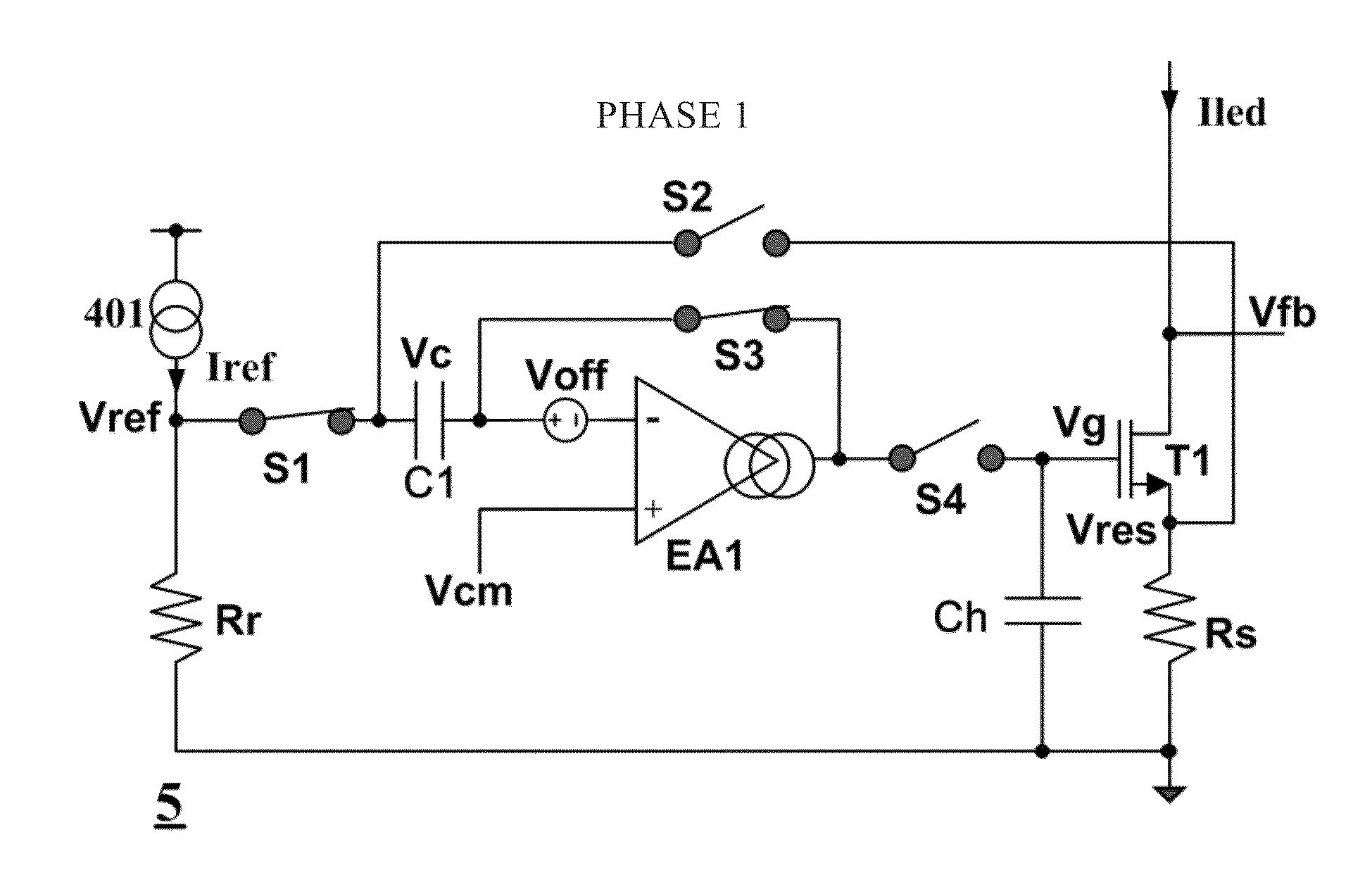
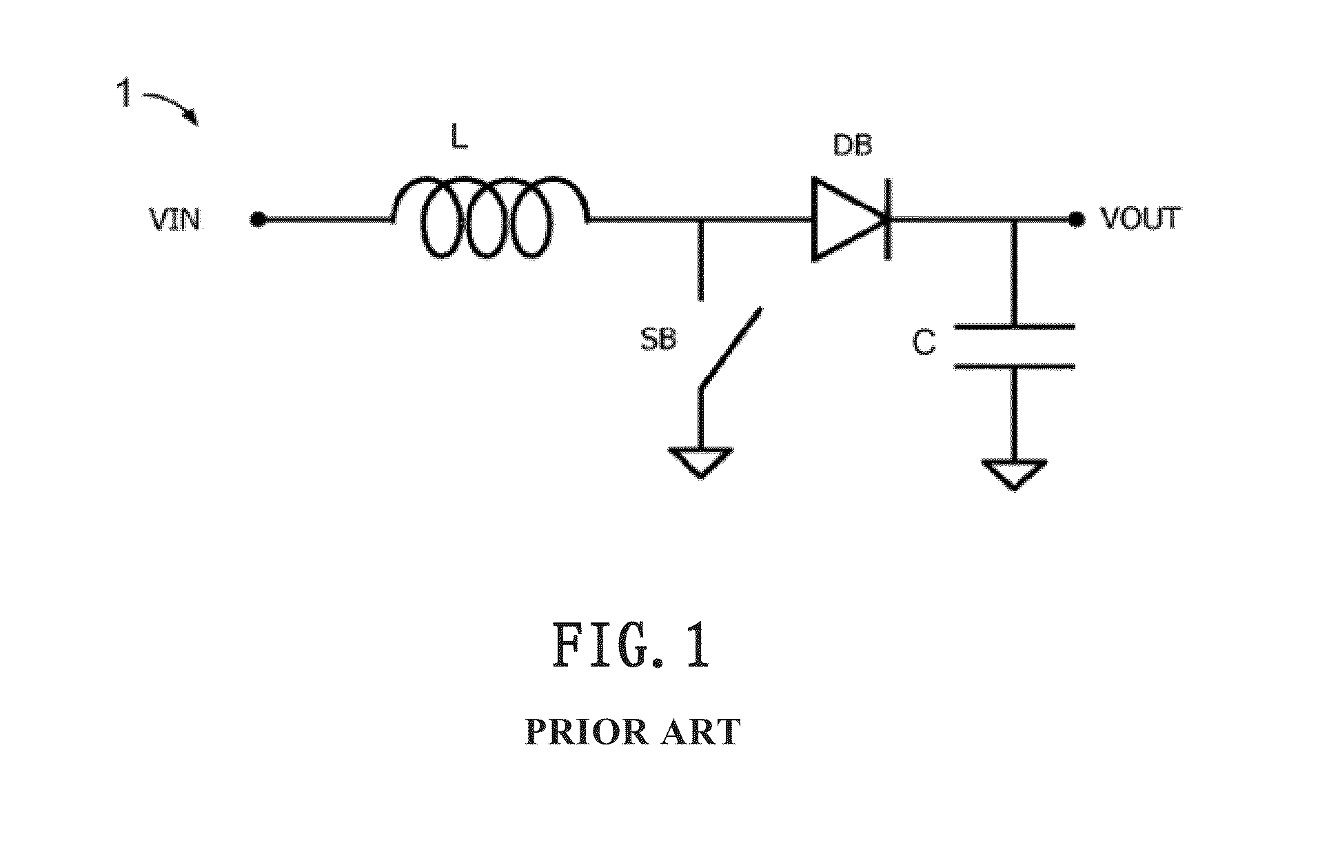
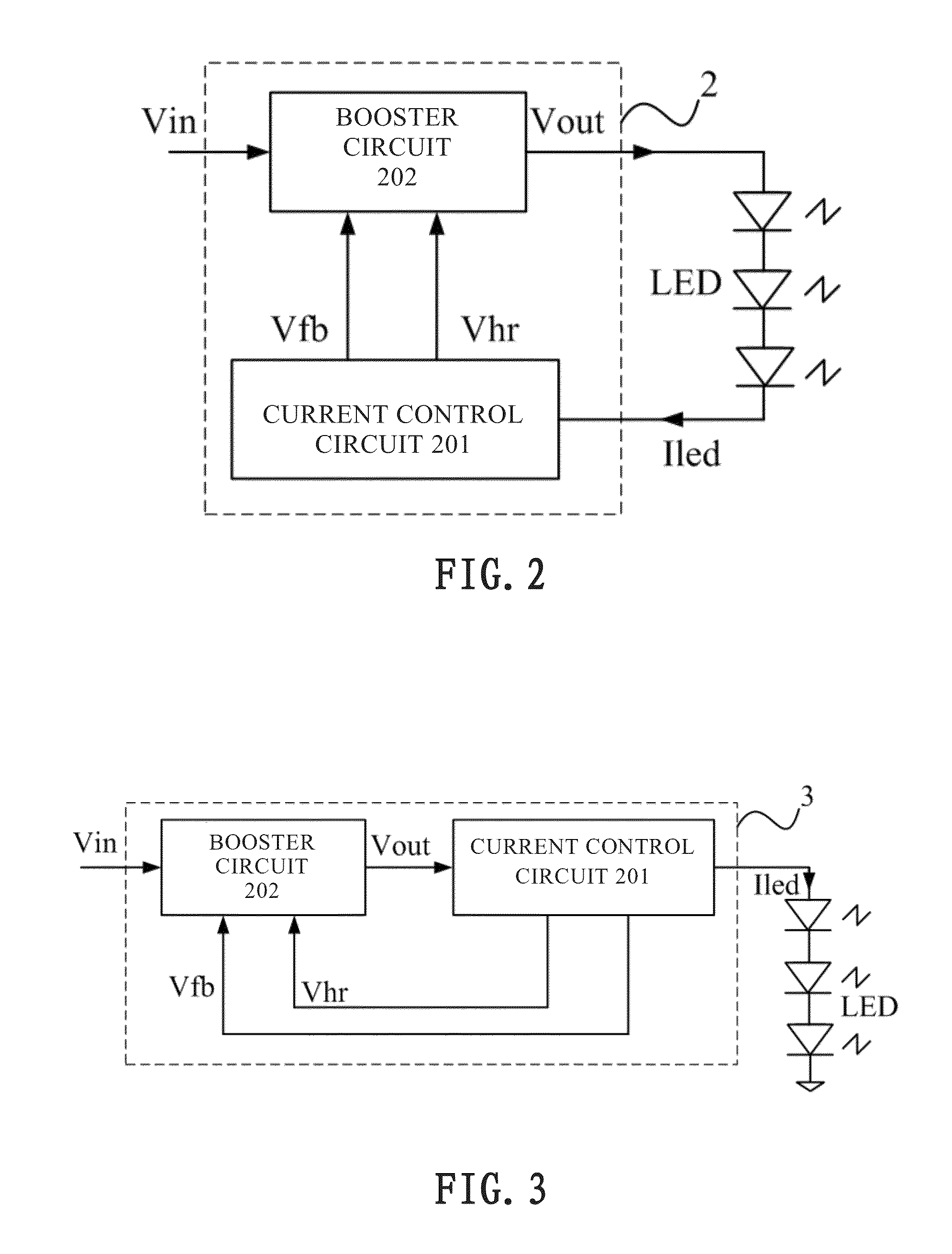
[0042]The preferred embodiments of the present disclosure will be described below with reference to the drawings.

[0043]It should be noted that the following detailed description set forth in conjunction with the accompanying drawings serves as description about some exemplary embodiments, but is not intended to completely describe all possible embodiments. It should be understood that the same or equivalent functions can be achieved by different embodiments. Moreover, the following description of at least one exemplary embodiment is merely illustrative and is in no way intended to limit the invention, its application or uses.

[0044]It should be noted that the relative arrangement of the components and steps, the numerical expressions, and numerical values set forth in these embodiments do not limit the scope of the present disclosure unless it is specifically stated otherwise. In all embodiments discussed herein, any particular values should be construed as illustrative and not limit...


PUM


Abstract

The present disclosure proposes a fully integrated accurate LED output current controlling circuit and method, which can be seamlessly combined with true PWM dimming. The current controlling circuit has an auto zero function in the light-emitting diode driver to eliminate offsets caused by the system, process variations, parasitic effects, dimming and so on in an LED driver application, and thus is capable of controlling the LED current with high accuracy. Moreover, the driver of the present disclosure does not require the use of external components such as an external resistor to regulate current accuracy.

Description

CROSS-REFERENCE TO RELATED APPLICATIONS[0001]This application claims priority to Chinese Patent Application No. 201110253164.1, filed on Aug. 31, 2011, which is incorporated herein by reference in its entirety.TECHNICAL FIELD[0002]The present disclosure generally relates to a driver for driving a light-emitting diode (LED), and more particularly, to a current controlling circuit in a LED driver for accurately controlling LED output current.DESCRIPTION OF THE RELATED ART[0003]Currently, fully integrated LED driver and current controlling products fail to accurately control LED driving current, because they do not take into consideration offset caused by the system, process variations, parasitic effects, dimming and so on. If a highly accurate current is required, an accurate external resistor needs to be used. However, a ground voltage offset, which varies with the LED output current is a mismatch source in the traditional external resistor-based method.[0004]Moreover, the traditiona...

Claims


Application Information

Patent Timeline
Patent Type & Authority Applications(United States)
IPC IPC(8): H05B33/08G05F1/46H05B44/00
CPCH05B33/0824G05F1/46H05B33/0842H05B45/44H05B45/397H05B45/38H05B45/325H05B45/347
Inventor SHAO, BINTOMIYOSHI, KENJI
Owner ANALOG DEVICES INT UNLTD
Why Eureka
Try Eureka