Pll using interpolative divider as digitally controlled oscillator

a technology of interpolation divider and digital control, applied in the direction of automatic control, electrical equipment, etc., can solve the problems of large silicon area being utilized, cross talk problems of lc oscillators with close frequencies

Active Publication Date: 2013-03-28
SKYWORKS SOLUTIONS INC
View PDF1 Cites 23 Cited by
  • Summary
  • Abstract
  • Description
  • Claims
  • Application Information

AI Technical Summary

Benefits of technology

[0005]Accordingly, at least some of the shortcomings of LC oscillator based PLLs are addressed in one or more embodiments described herein.

Problems solved by technology

However, putting multiple PLLs on a single integrated circuit can result in a large silicon area being utilized, particularly if the PLLs utilize LC voltage controlled oscillators.
In addition, LC oscillators with close frequencies can have cross talk problems.

Method used


Image

  • Pll using interpolative divider as digitally controlled oscillator
  • Pll using interpolative divider as digitally controlled oscillator
  • Pll using interpolative divider as digitally controlled oscillator

Examples


Embodiment Construction

)

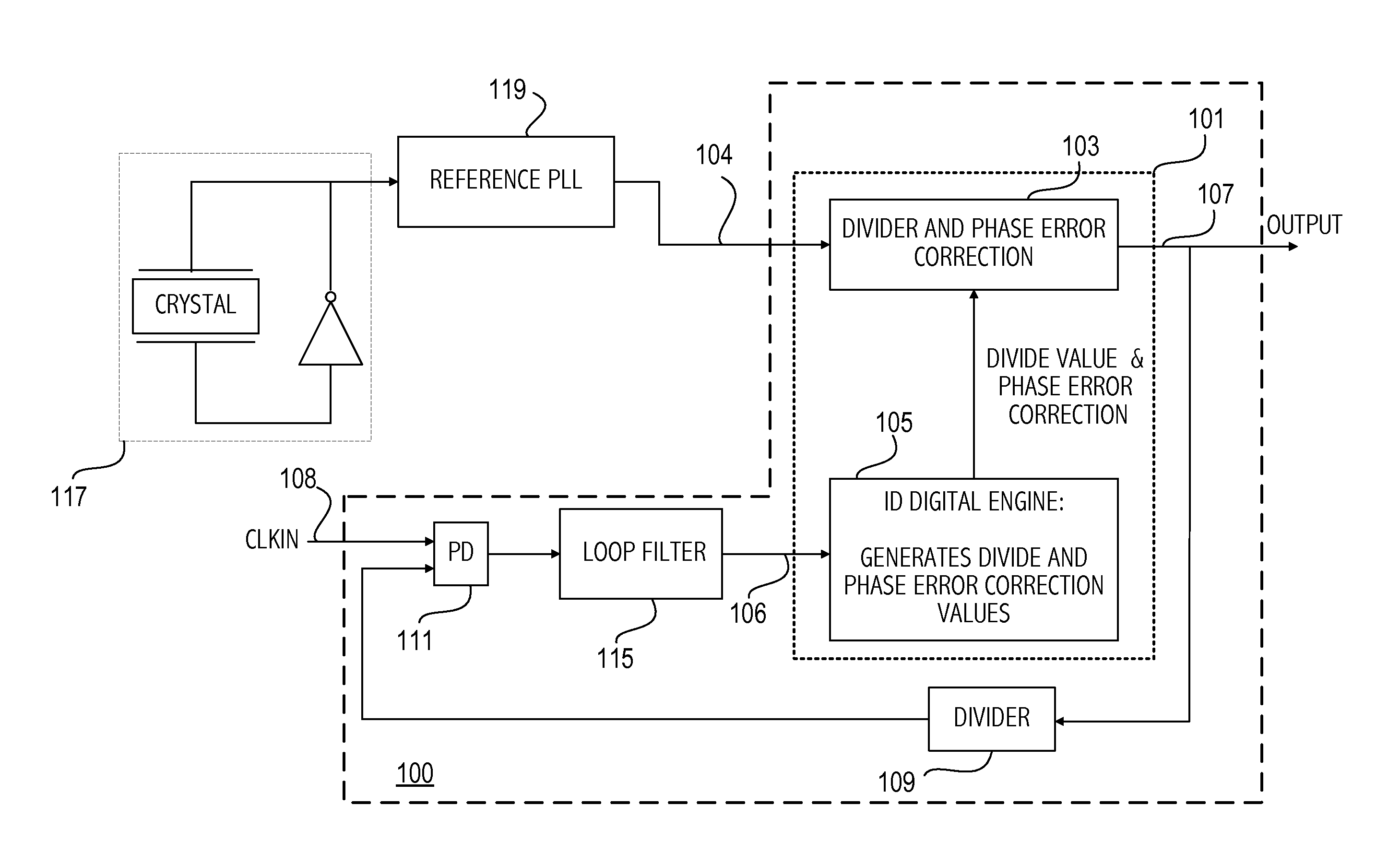
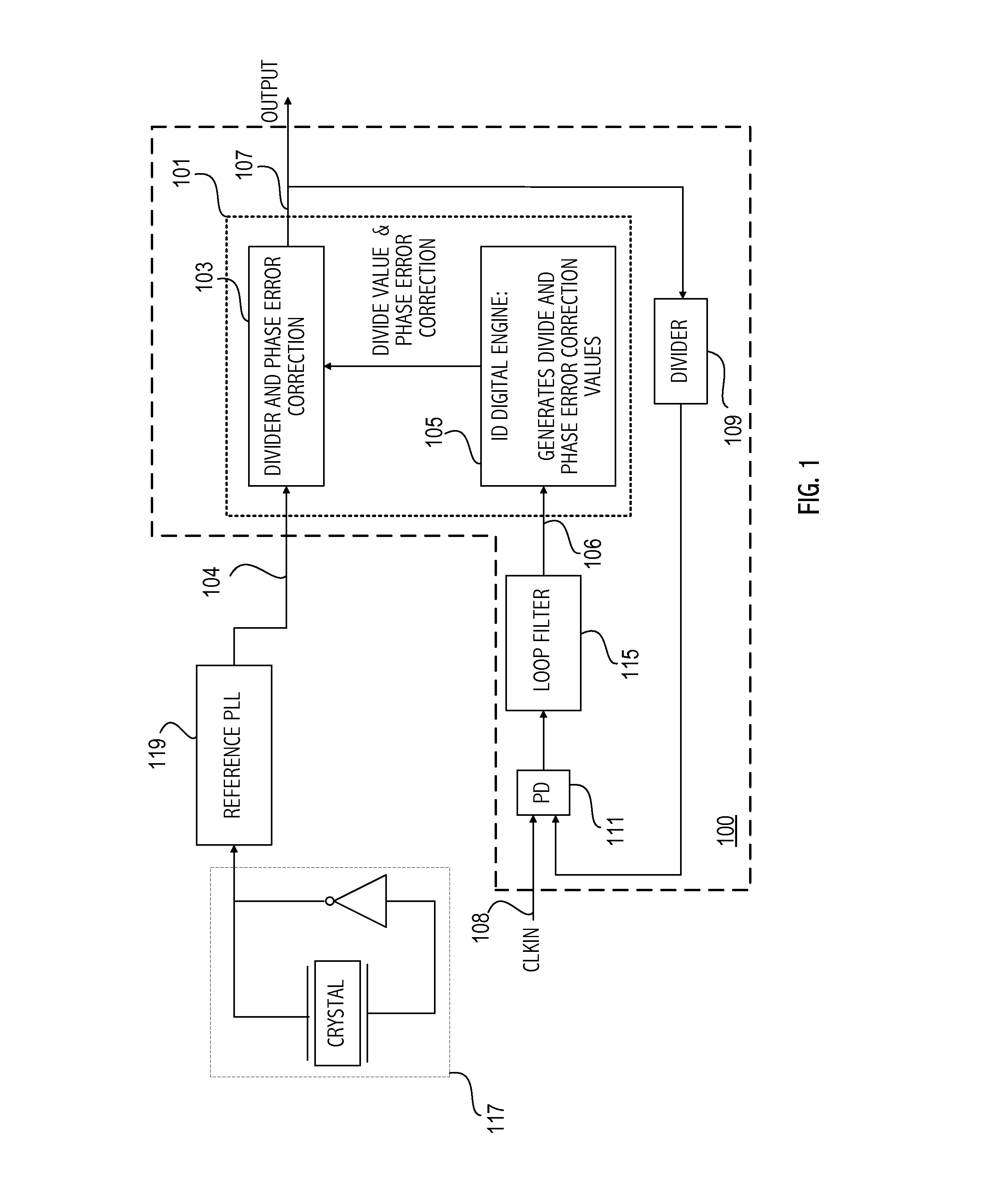
[0015]FIG. 1 illustrates an embodiment in which PLL 100 incorporates an interpolative divider 101 as a digitally controlled oscillator (DCO). The interpolative divider 101 includes a divider and phase interpolator 103 and a control block 105, which are explained in more detail herein. The interpolative divider 101 divides an input signal 104 according to a divide ratio 106 and supplies an output signal 107. The output 107 of the interpolative divider is supplied to a feedback divider 109 of the PLL 100. The feedback divider supplies phase detector 111. Note that the feedback divider, while shown in FIG. 1, may be omitted in other embodiments, in which case the output of the interpolative divider is coupled directly to the phase detector. The phase detector also receives as an input signal CLKIN to which the PLL is designed to lock. The phase detector supplies a phase error signal reflecting the difference between the CLKIN signal and the feedback signal to loop filter 115, which in...


PUM


Abstract

One or more PLLs are formed on an integrated circuit. Each PLL includes an interpolative divider configured as a digitally controlled oscillator, which receives a reference clock signal and supplies an output signal divided according to a divide ratio. A feedback divider is coupled to the output signal of the interpolative divider and supplies a divided output signal as a feedback signal. A phase detector receives the feedback signal and a clock signal to which the PLL locks. The phase detector supplies a phase error corresponding to a difference between the clock signal and the feedback signal and the divide ratio is adjusted according to the phase error.

Description

BACKGROUND[0001]1. Field of the Invention[0002]This invention relates to generation of clock signals and more particularly to generating clock signals using phase-locked loops with interpolative dividers.[0003]2. Description of the Related Art[0004]High speed, high port density networking applications require multiple jitter attenuating phase-locked loops (PLLs). Markets for such devices include the 10 Gigabit, 40 Gigabit, and 100 Gigabit telecom / datacom infrastructure. However, putting multiple PLLs on a single integrated circuit can result in a large silicon area being utilized, particularly if the PLLs utilize LC voltage controlled oscillators. In addition, LC oscillators with close frequencies can have cross talk problems.SUMMARY[0005]Accordingly, at least some of the shortcomings of LC oscillator based PLLs are addressed in one or more embodiments described herein.[0006]One embodiment includes an interpolative divider configured to receive a first input signal and supply an out...

Claims


Application Information

Patent Timeline
Patent Type & Authority Applications(United States)
IPC IPC(8): H03L7/06
CPCH03L7/1974H03L7/0992
Inventor HARA, SUSUMUELDREDGE, ADAM B.FU, ZHUOWILSON, JAMES E.
Owner SKYWORKS SOLUTIONS INC
Why Eureka
Try Eureka