Stub array microstrip line phase shifter

a phase shifter and microstrip technology, applied in delay lines, waveguides, electrical equipment, etc., can solve problems such as power handling and other issues, many electronic components, such as diodes and surface mount phase shifters, are not suited to signals, and components may experience excessive heating

Inactive Publication Date: 2013-03-28
HONG KONG APPLIED SCI & TECH RES INST
View PDF2 Cites 17 Cited by
  • Summary
  • Abstract
  • Description
  • Claims
  • Application Information

AI Technical Summary

Benefits of technology

[0010]An isolation structure of embodiments of the invention provides electrical isolation between one or more component of the microstrip lin

Problems solved by technology

Providing signal phase shifting in some systems may present power handling and other issues.
Many electronic components, such as diodes and surface mount phase shifters, are not suited for signals at such power levels (e.g., the components may experience excessive heating, be destroyed, provide unacceptable signal distortion, etc.).
The foregoing mechanical phase shifter configurations tend to be quite lossy.
Accordingly, a significant amount of the signal power is lost in the phase shifters.
The f

Method used


Image

  • Stub array microstrip line phase shifter
  • Stub array microstrip line phase shifter
  • Stub array microstrip line phase shifter

Examples


Embodiment Construction

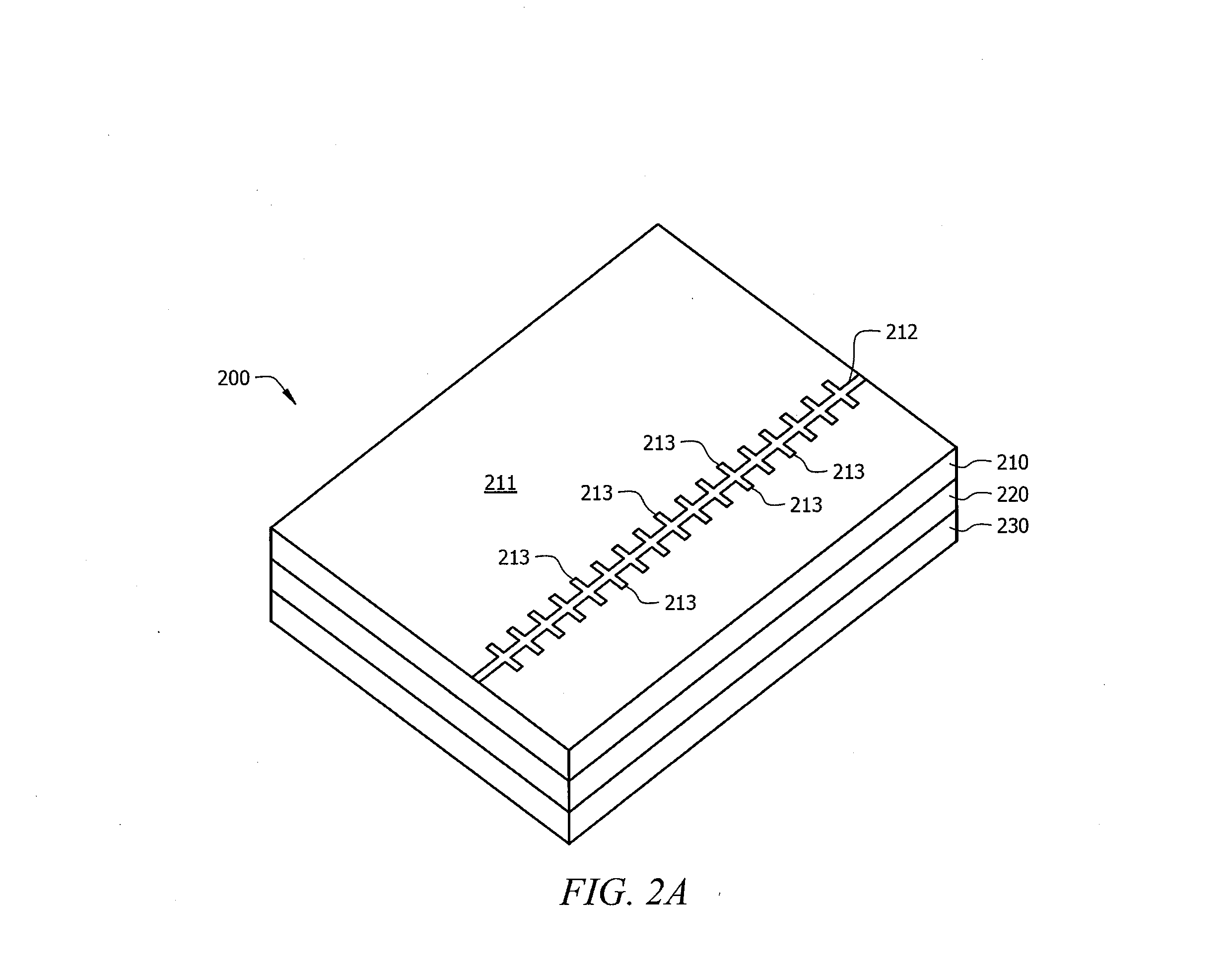
[0023]FIGS. 2A-2C show a stub array microstrip line phase shifter of embodiments of the invention. As shown in FIG. 2A, stub array microstrip line phase shifter 200 of the illustrated embodiment comprises microstrip line structure 210, isolation structure 220, and phase tuning structure 230. Microstrip line structure 210, isolation structure 220, and phase tuning structure 230 are provided in a stacked configuration adapted for cooperative operation to provide phase shifting of signals transmitted by stub array microstrip line 212 of microstrip line structure 210. Exploded views of this stacked configuration of structures are shown in FIGS. 2B and 2C, wherein FIG. 2B shows an exploded view from the top and FIG. 2C shows an exploded view from the bottom.

[0024]Microstrip line structure 210 comprises stub array microstrip line 212 providing a signal path for transmission of signals (e.g., RF signals) between interfaces A and B. As can be seen in FIGS. 2A and 2B, stub array microstrip l...


PUM


Abstract

Systems and methods which utilizes a stub array microstrip line for providing a phase shifter configuration are shown. A stub array microstrip line phase shifter of embodiments may comprises a microstrip line structure, an isolation structure, and a phase tuning structure cooperative to provide phase shifting of signals passed through the microstrip line structure. A microstrip line structure comprises a stub array microstrip line having a plurality of microstrip stubs provided in association with a slotted ground plane having a plurality of slots. The stub array microstrip line is adapted to provide compensation for capacitance and/or inductance associated with the slots of the slotted ground plane. A phase tuning structure provides coupling of signals transmitted by the stub array microstrip line to the slots of the slotted ground plane for signal phase shifting.

Description

TECHNICAL FIELD[0001]The invention relates generally to phase shifting signals and, more particularly, to providing signal phase shifting using a stub array microstrip line.BACKGROUND OF THE INVENTION[0002]Shifting the phase of signals, such as radio frequency (RF) signals used in modern communication systems, is often used in various signal processing techniques. For example, signals provided to or from individual elements of an antenna array may each be phase shifted to provide desired phase relationships for beam forming. Likewise, signals provided to or from individual elements of an antenna array may be phase shifted to provide phase relationships for beam tilting (e.g., downward tilt for cellular telecommunications coverage).[0003]For example, a cellular base station antenna array may employ electrical down-tilt, as may be provided through the use of appropriate phase shifting, to provide communication coverage within a designated portion of a cellular provider's service area ...

Claims


Application Information

Patent Timeline
IPC IPC(8): H01P1/18
CPCH01P1/184
Inventor LAI, HAU W.MAK, ANGUS C. K.ROWELL, CORBETT R.
Owner HONG KONG APPLIED SCI & TECH RES INST
Why Eureka
Try Eureka