
Reciprocal method two-way wave equation targeted data selection for improved imaging of complex geologic structures

a geologic structure and data selection technology, applied in the field of seismic imaging of subsurface geologic structures, can solve the problems of complex geologic structures that may only be complex, difficult to solve complex structures, difficult to solve what, etc., and achieve the effect of better imaging of the targ

Active Publication Date: 2013-03-28
CONOCOPHILLIPS CO
View PDF2 Cites 15 Cited by
  • Summary
  • Abstract
  • Description
  • Claims
  • Application Information

AI Technical Summary

Benefits of technology

This invention relates to a process for improving the imaging of seismic data that is obscured or complicated by structures. Here are the steps: a) create a geological model of the structure and the area of interest; b) select seismic source and receiver locations for evaluation with the model; c) select parameters for energy propagation; d) compute the energy propagation from the target to the receivers using reciprocity; e) display the energy and attributes that are received by the receivers from the selected source; f) analyze the displays and identify the source / receiver pair that provides better imaging of the target; and g) create geological images of the substructure using the identified source / receiver pair data. This invention can help to better understand the structure and the energy that is propagated through it, which can aid in identifying and imaging potential oil or gas reservoirs.

Problems solved by technology

Complex geologic structures may only be complex in that it is difficult to resolve the complex structure using seismic imaging or difficult to resolve what is beneath the complex structure using seismic surveying, or both.
Gas attenuates compressive waves and, to the extent any compression waves are reflected back to the surface, they are noisy and essentially undecipherable.
Big gas deposits may actually create seismic “black holes” hiding or obscuring large areas that could hold significant hydrocarbon deposits.
Substantial amounts of hydrocarbons may end up trapped at the interface of a salt dome and a hydrocarbon bearing formation, especially where the interface is under the overhang of a mushroom-shaped salt dome.
Since compression waves travel relatively slow through rock, but comparatively fast through salt, seismic energy that has passed through a salt formation, especially a salt formation with an irregular or complicated shape appears scattered in ways that are not easily resolvable into a coherent image.
Conventional techniques of survey modeling and survey design are not particularly well suited for complex geological situations or for the problems mentioned above.
The problem is that the ray trace methods assume that the rays are traveling through homogenous media and reflect or refract at the bed interfaces.
Ray trace modeling follows direct lines and does not handle compaction curves cleanly.
Ray tracing also does not handle anisotropy well and does not allow accurate representation of dispersion.
However, full wave equation modeling is far more accurate in its portrayal of seismic energy, and could provide far more accurate images, but computer resources and coding has heretofore been unavailable for reasonable sized acquisition or imaging modeling projects.

Method used


Image

  • Reciprocal method two-way wave equation targeted data selection for improved imaging of complex geologic structures
  • Reciprocal method two-way wave equation targeted data selection for improved imaging of complex geologic structures
  • Reciprocal method two-way wave equation targeted data selection for improved imaging of complex geologic structures

Examples


Embodiment Construction

[0014]Turning now to the detailed description of the preferred arrangement or arrangements of the present invention, it should be understood that the inventive features and concepts may be manifested in other arrangements and that the scope of the invention is not limited to the embodiments described or illustrated. The scope of the invention is intended only to be limited by the scope of the claims that follow.

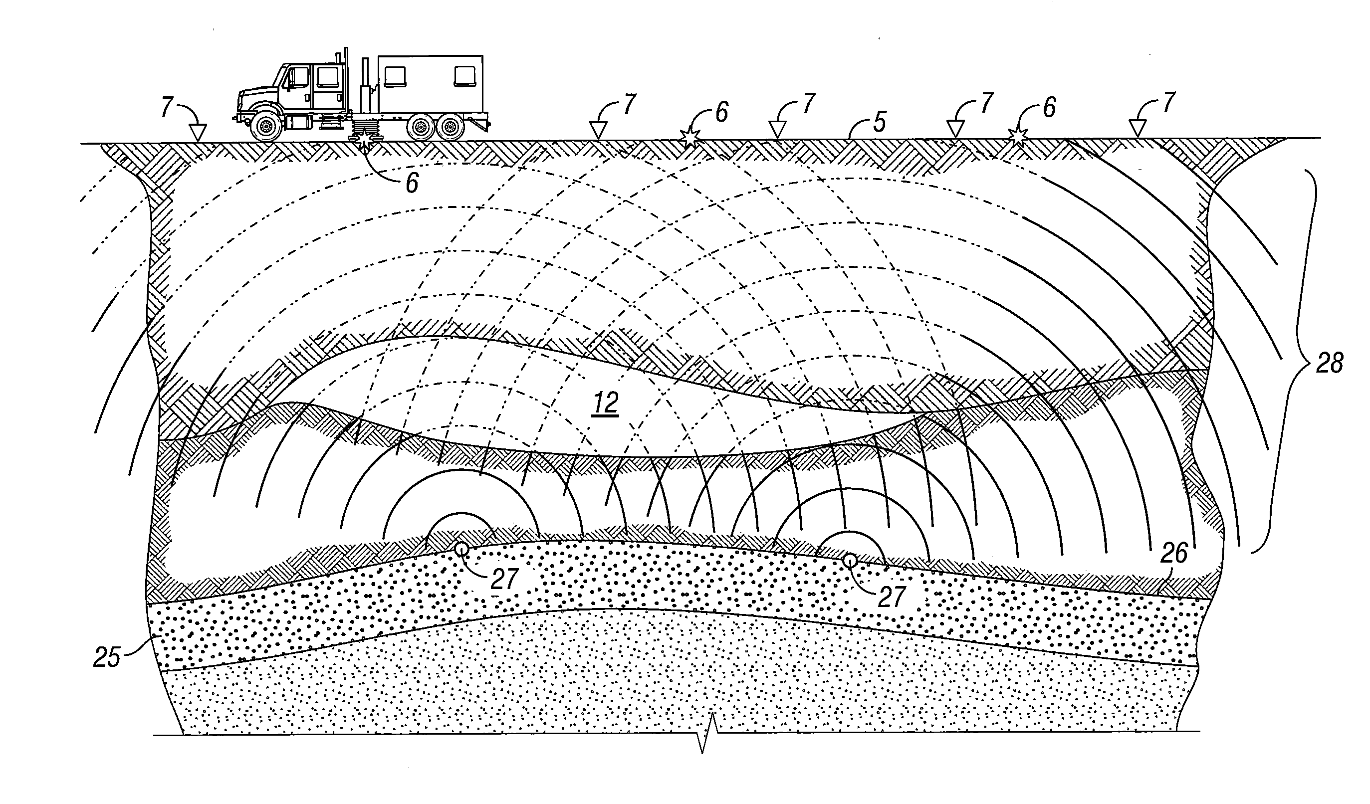
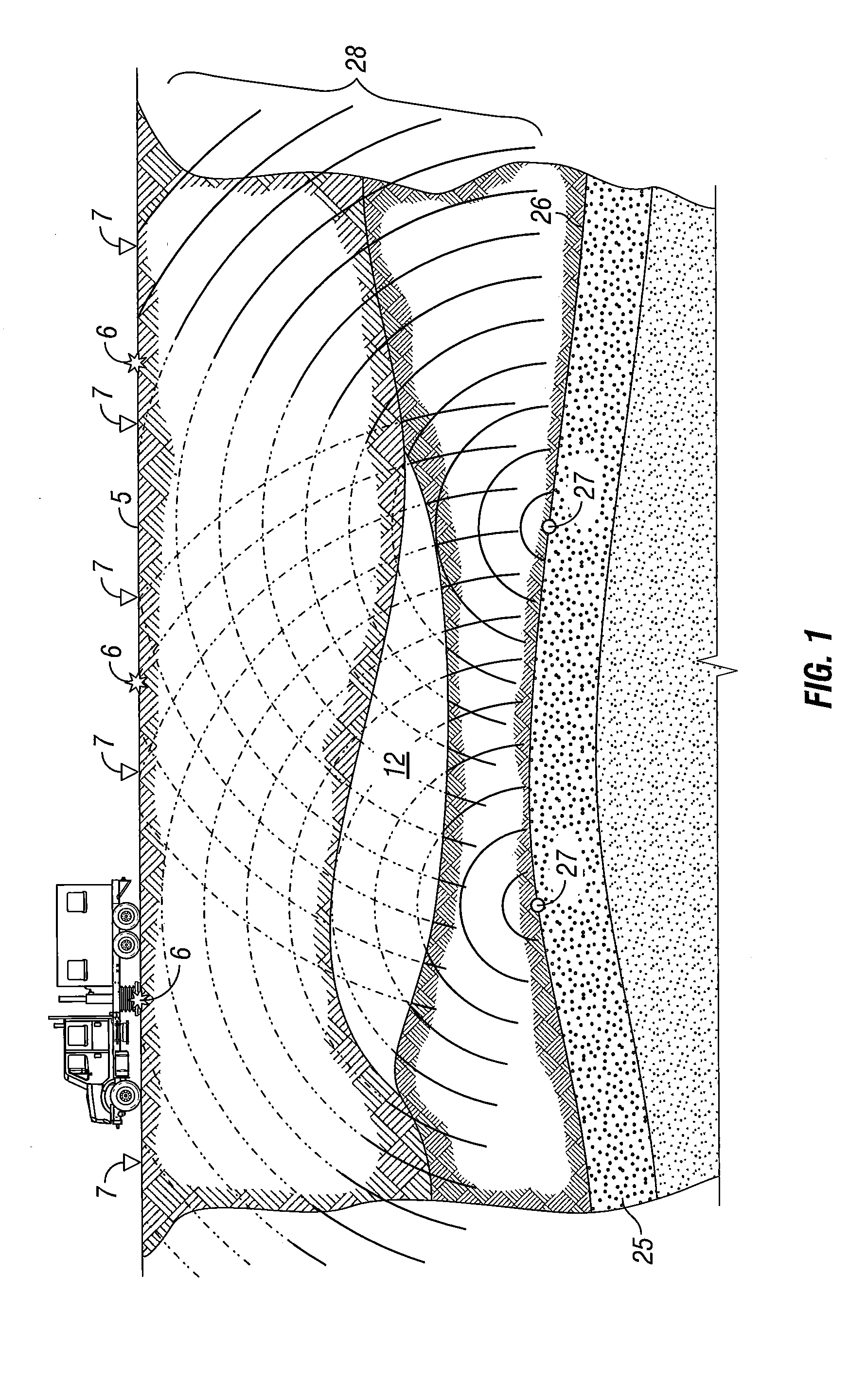
[0015]In FIG. 1, a gas-containing structure is indicated by the number 12 underlying the surface of the earth 5. Below the gas-containing structure 12 is a prospect indicated by the number 25 having an inverted cup shape. Interest in the prospect 25 arises because the inverted cup shape may form a trap where liquid hydrocarbons may collect and pool. However, the gas containing structure 12 may also be caused by gas leaking from the prospect. If the prospect 25 truly has an inverted cup shape with porous rock below an impermeable layer above, the prospect 25 may be a prime tar...


PUM


Abstract

The invention relates to seismic imaging where complex geologies are likely to create data that is confusing or ambiguous for a conventional matrix of acquisition source points and receiver locations. With some understanding of the geological substructure, the acquisition source points and receiver locations that optimize the imaging may be found by using a reciprocal two-way wave equation propagation method coupled with a quality geologic model. With this, the acquisition source points and receiver locations that optimize the imaging may be selected and used to better resolve the substructure and avoid the inclusion of data that obscures understanding of the substructure.

Description

CROSS-REFERENCE TO RELATED APPLICATIONS[0001]This application is a non-provisional application which claims benefit under 35 USC §119(e) to U.S. Provisional Application Ser. No. 61 / 540,368, filed Sep. 28, 2011, entitled “Reciprocal Method Two-Way Wave Equation Targeted Data Selection for Improved Imaging of Complex Geologic Structures,” which is incorporated herein in its entirety.[0002]This invention is related to U.S. Provisional Application Ser. No. 61 / 491,034, filed May 27, 2011, entitled “Two Way Wave Equation Targeted Data Selection for Improved Imaging of Prospects Among Complex Geologic Structures,” U.S. Provisional Patent Application Ser. No. 61 / 491,050, filed May 27, 2011 entitled “Two-Way Wave Equation Targeted Data Selection for Seismic Acquisition of Complex Geologic Structures” and U.S. Provisional Patent Application Ser. No. 61 / 540,348, filed Sep. 28, 2011, entitled “Reciprocal Method Two-Way Wave Equation Targeted Data Selection for Seismic Acquisition of Complex Geo...

Claims


Application Information

Patent Timeline
Patent Type & Authority Applications(United States)
IPC IPC(8): G01V1/28
CPCG01V1/28G01V2210/67G01V1/003G01V2210/679G01V99/005G01V2210/673G01V2210/675G01V1/345G01V20/00
Inventor CAO, JUNBREWER, JOEL D.MOSHER, CHARLES C.EICK, PETER M.
Owner CONOCOPHILLIPS CO
Learn More