Ball-Type Coupling Device For Coupling Two Sliding Shafts With Pivoting Support

a coupling device and sliding shaft technology, which is applied in the direction of shafts, couplings, bearings, etc., can solve the problems of deteriorating performance affecting the service life of the device, and requiring more assembly time and labor to assemble the coupling device, so as to reduce the axial force, ensure enhanced wear characteristics, and accurate variability in the length of the coupling device

Active Publication Date: 2013-03-28
ROBERT BOSCH AUTOMOTIVE STEERING VENDOME SAS
View PDF2 Cites 6 Cited by
  • Summary
  • Abstract
  • Description
  • Claims
  • Application Information

AI Technical Summary

Benefits of technology

[0009]Another object of the present invention is to provide an improved coupling device with improved wear characteristics and reduced play between the inner and outer shafts over the life of a vehicle.
[0010]Another object of the present invention is to provide an improved coupling device that may be easily mounted on existing motor vehicles by reducing the axial force required for installation.
[0011]Yet another object of the invention is to provide an improved coupling device where elastic members are not involved in the transmission of the torque, in order to preserve high angular rigidity of the coupling device.
[0016]In order to increase the operating safety of the coupling device of the invention, male grooves and female grooves with curved profiles having some clearance, are laid out on the inner shaft and on the outer shaft, so that in the case that the balls fail, the torque may still be transmitted between the inner shaft and the outer shaft.
[0030]The device for coupling two shafts along their common axis according to the invention thus has the advantage of always having two bearing areas for each of the two inner and outer shafts and for each row of balls, which are always in contact even if there is no transmission of a torque.
[0031]Further, there is a reduced axial force which is required for assembly. The accurate variability in length of the coupling device of the invention gives the possibility of avoiding axial jerks during the driving of the vehicle, and guarantees enhanced wear characteristics while avoiding the occurrence of coupling play. Further, when torque is transmitted through the device, the axial force necessary to vary the length is considerably reduced because of the rolling and sliding contact. Additionally, the torque transmission is not directly influenced by the elastic members, because the elastic members are not involved in the transmission of the torque. This allows the coupling device to retain strong angular rigidity during torque transmission. The coupling device may also be easily mounted in existing motor vehicle steering columns.

Problems solved by technology

However, this type of device develops wear over the life of the vehicle.
The tight tolerancing requires a relatively large axial force for proper assembly, hence a longer assembly time and more labor required to assemble the coupling device.
This solution poses problems for absorbing axial movements when the torque on the shaft is high, as the sliding forces increase proportionally with the friction forces between both splined portions.
Moreover, the wear of the plastic parts leaves play between the shafts, which causes deteriorated performance of the coupling device.
This solution is satisfactory for the sliding, under a torque with a relatively low axial force, but it poses problems in terms of angular rigidity because the torsional stiffness is directly proportional to the stiffness of the pre-tensioning of the springs.
These jerks are detrimental to maintaining proper adjustment of the axial sliding while maintaining reduced rotational play.
The jerks are further harmful to driving and handling performance.

Method used


Image

  • Ball-Type Coupling Device For Coupling Two Sliding Shafts With Pivoting Support
  • Ball-Type Coupling Device For Coupling Two Sliding Shafts With Pivoting Support
  • Ball-Type Coupling Device For Coupling Two Sliding Shafts With Pivoting Support

Examples


Embodiment Construction

[0048]The invention relates to a rotatable coupling device for two shafts, the shafts sliding within each other along their common axis.

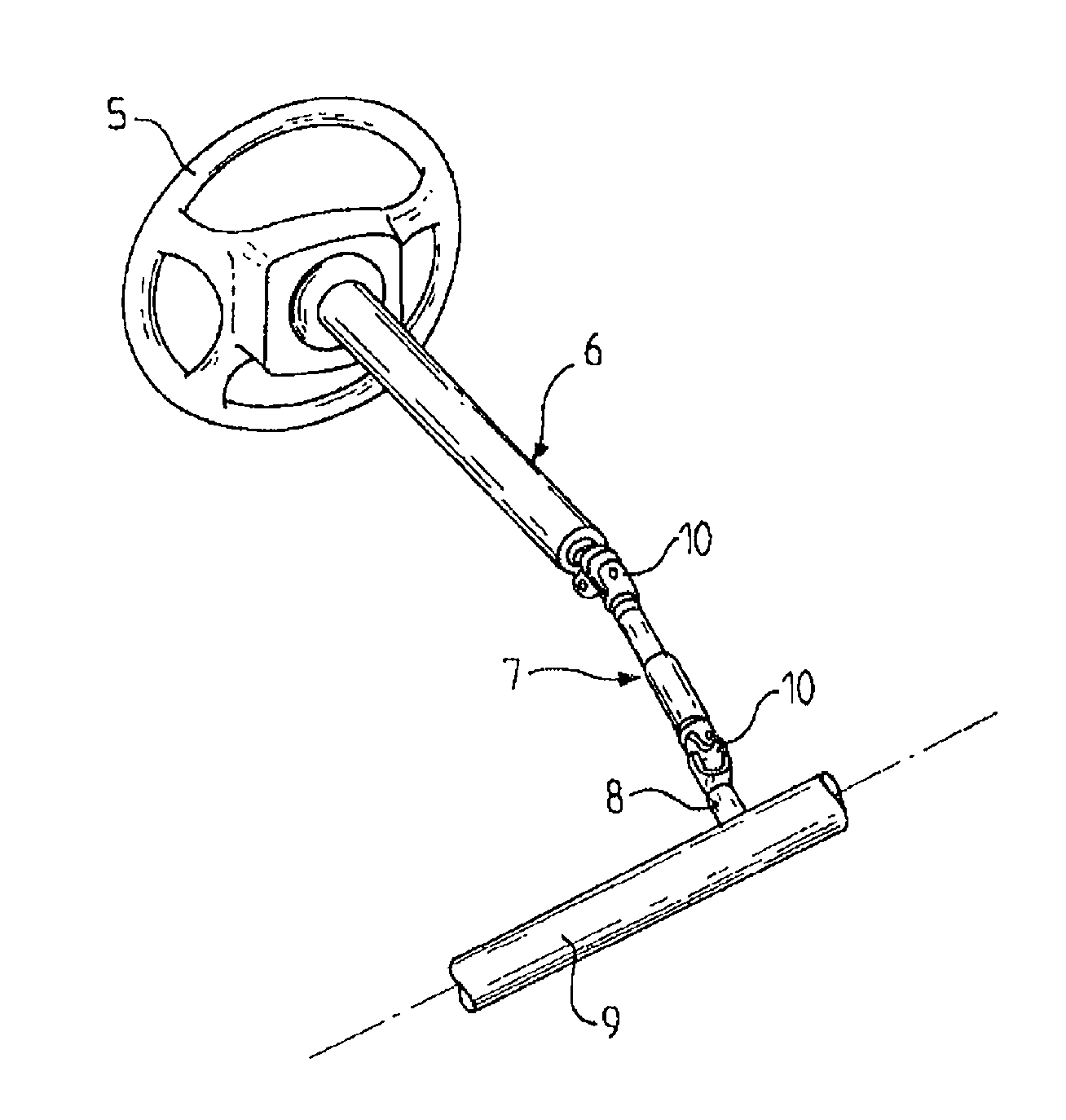
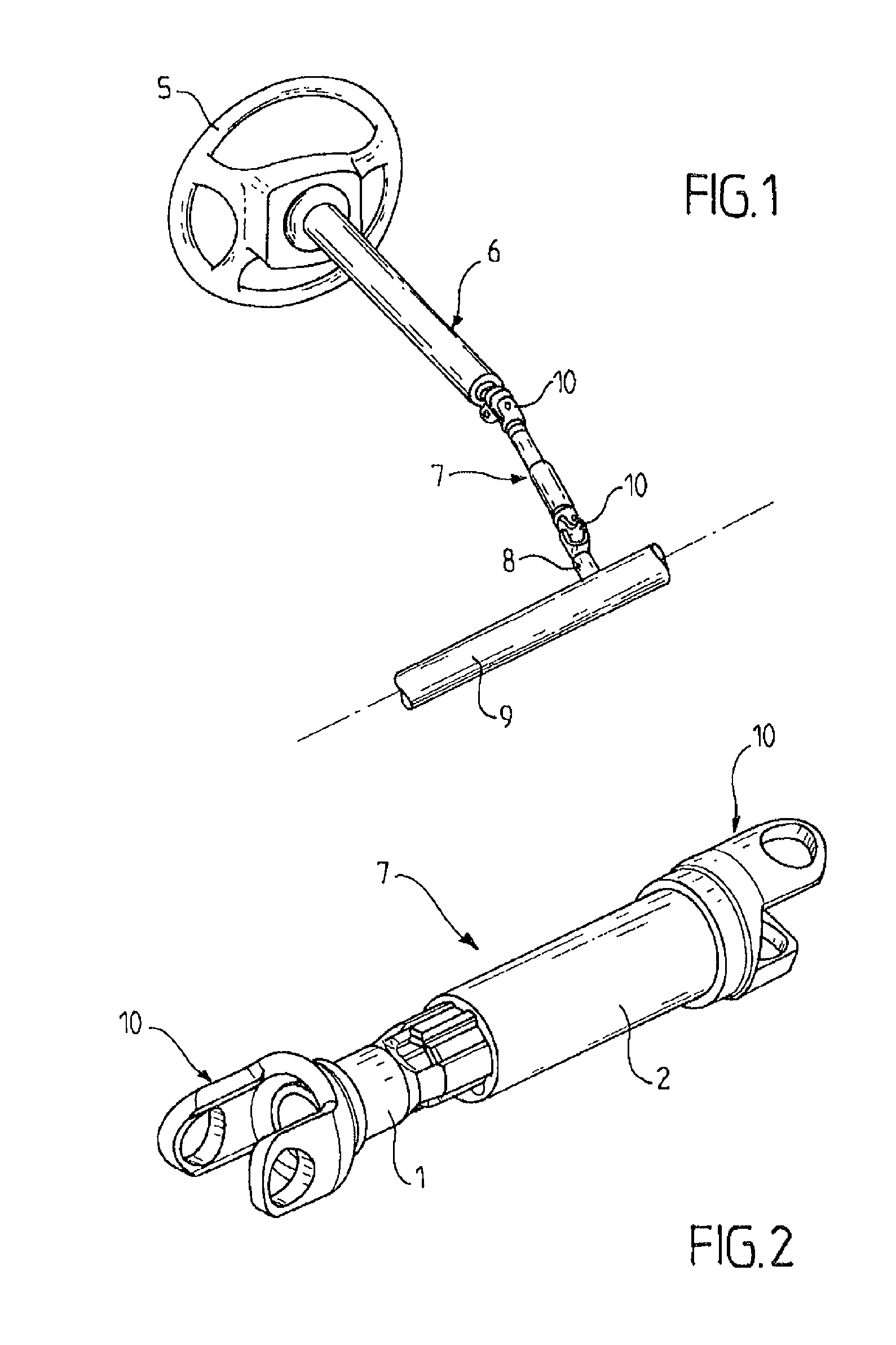
[0049]This coupling device is particularly well applied to a motor vehicle steering system, as the one which is schematically illustrated in FIG. 1.

[0050]FIG. 1 shows a steering system including a steering column with an upper column portion 6 also called upper column, and an intermediate column portion 7 also called intermediate axis. The upper column portion 6 is connected through its upper end to the steering wheel 5, and through its lower end to the intermediate column portion 7. The intermediate column portion 7 is connected through its upper end to the upper column portion 6, and through its lower end to the steering gear case 8 of the steering stem 9. The intermediate column portion 7 is connected at each of its ends by means of a Cardan joint hinge referenced as 10 for the upper column portion 6 and also referenced as 10 for the steering gea...


PUM


Abstract

Device for coupling an inner shaft and an outer shaft which slide along their common axis with balls positioned between the two shafts. The balls rest directly in axial grooves of the outer shaft and on two rails positioned in axial grooves of the inner shaft. The two rails pivot about the balls, by pressing against flanks of mating curved profile of the axial groove, and are held in place by an elastic element which presses against the bottom of the axial groove.

Description

FIELD OF THE INVENTION[0001]The invention relates to a rotatable coupling device for two shafts sliding along their common axis. The coupling device of the invention is applied to a motor vehicle steering column, by adapting it to the intermediate column portion connected to the steering gear case, or to the upper column portion connected to the steering wheel.BACKGROUND OF THE INVENTION[0002]Vehicle steering columns are assembled from a number of universal or Cardan joints. Typically, an intermediate axis of a steering column has a Cardan joint at each end: one Cardan joint is connected to the motion input of the steering gear case, and the other Cardan joint is connected to the upper column. In order for the steering mechanism to function properly, the length of the intermediate axis must be variable. The variability of the intermediate column is adapted to oscillations of the front of the vehicle. These oscillations are due to the profile and the surface condition of the road. A ...

Claims


Application Information

Patent Timeline
Patent Type & Authority Applications(United States)
IPC IPC(8): F16C3/035
CPCF16C3/035F16D3/065F16C29/123F16C29/04F16C2326/24
Inventor FEVRE, LAURENTCAPELA, DAVID
Owner ROBERT BOSCH AUTOMOTIVE STEERING VENDOME SAS
Why Eureka
Try Eureka