Cardiovascular device

a heart valve and vascular technology, applied in the field of heart valve devices, can solve the problems of reducing the blood supply to vital organs, and suffering from certain drawbacks of the above described prior art, and achieve the effect of stably fitting on site and quick remedying heart failur

Active Publication Date: 2013-03-28
PARRAVICINI ROBERTO
View PDF1 Cites 0 Cited by
  • Summary
  • Abstract
  • Description
  • Claims
  • Application Information

AI Technical Summary

Benefits of technology

[0012]Another object of the invention is to provide a cardiovascular device that can quickly remedy heart failure caused by a heart dilating disease.
[0013]Yet another object of the invention is to provide a cardiovascular device that can be stably fitted on site by a surgical procedure that sub

Problems solved by technology

Such enlargement of the left ventricle causes a blood pressure drop and hence dangerously reduces blood supply to vital organs, such as lungs, brain and kidneys.
The above described prior art suffers from certain drawbacks.
A first drawback concerning transplantation is that it is not always easy to find a donor that can provide an organ for transplantation and that the death of the donor is always implied.
Another drawback, concerning the use of an auxiliary pump apparatus, co

Method used


Image

  • Cardiovascular device
  • Cardiovascular device
  • Cardiovascular device

Examples


first embodiment

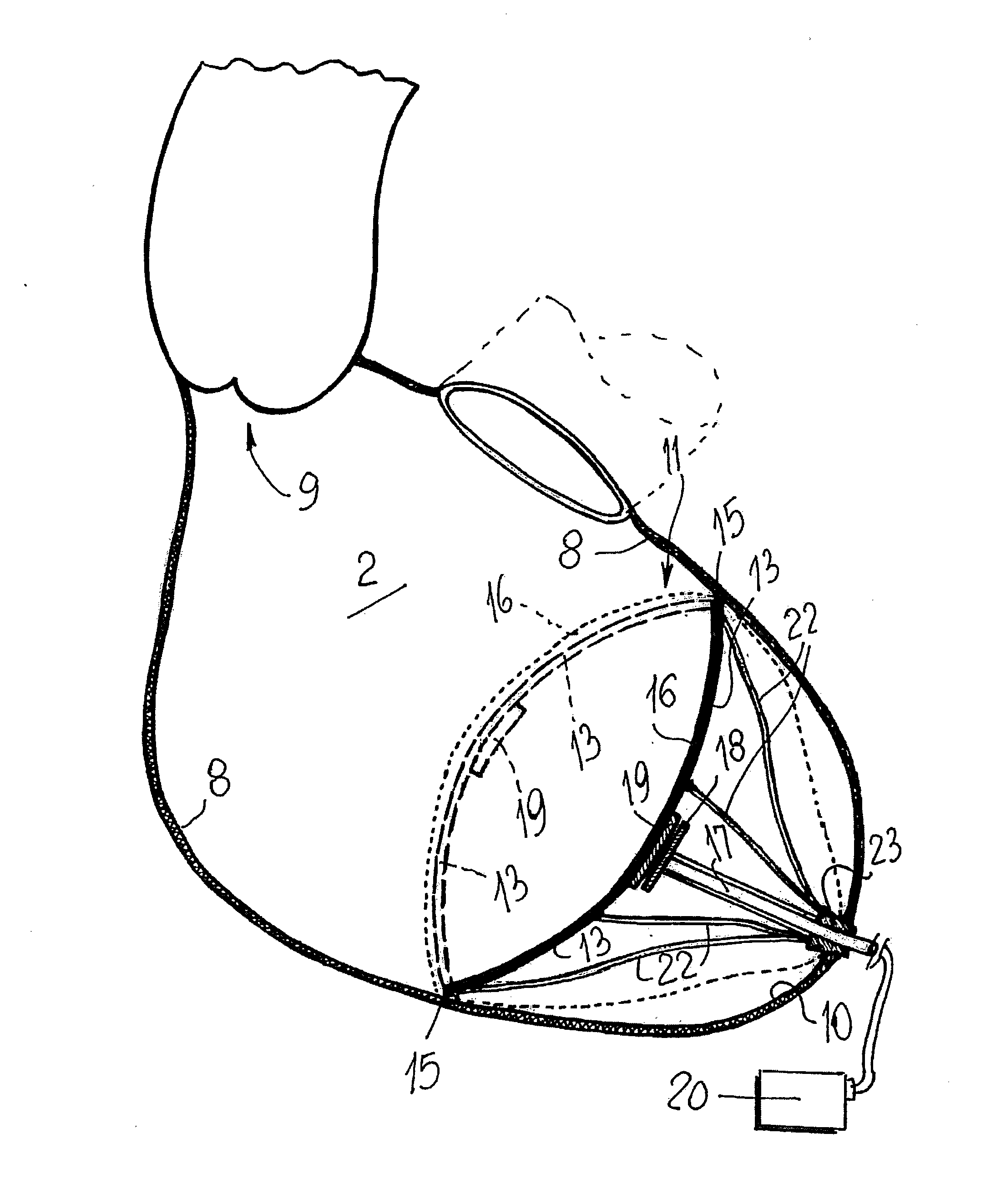
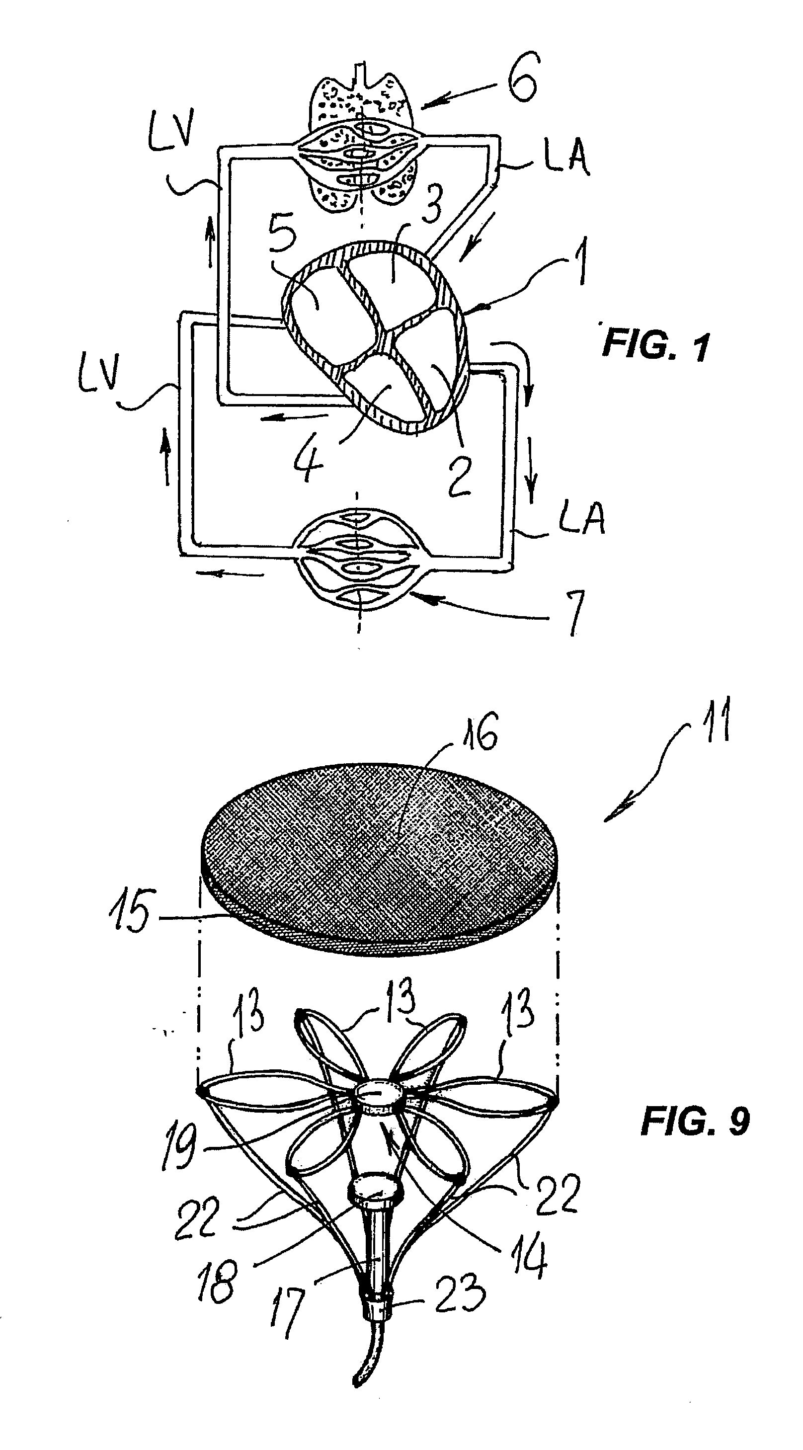
[0030]Referring to FIGS. 3 to 7, the cardiovascular device is shown to comprise a rectangular frame 12 composed of a plurality of radially arranged arms 13 which have converging ends ending up into a first central hub 14 with which they are hinged, and opposite ends that are hinged to a peripheral edge 15 which is designed to abut against and sealingly engage the walls of the ventricle 2, in which it can be typically integrated with time.

[0031]The cardiovascular device 11 has such an overall transverse dimension as to be fitted transverse to the larger dimension “D1” of the ventricle 1, thereby partially reducing the overall internal volume thereof.

[0032]A flexible sheet element 16, namely a diaphragm, stretching from the peripheral edge 15 and supported by the arms 13, is attached to the frame 12.

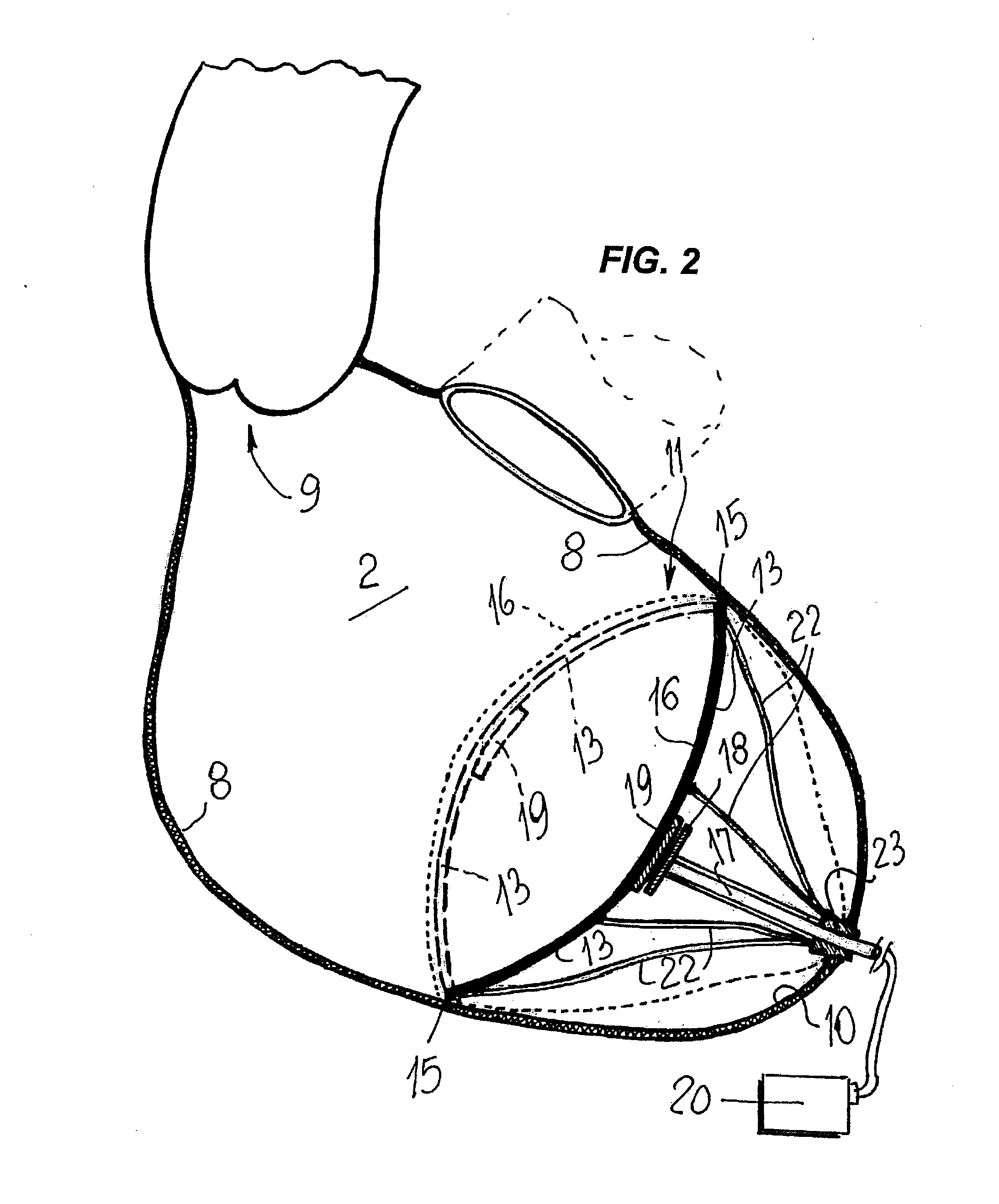
[0033]As better shown in FIG. 2, in an alternative embodiment of a vascular device 11, a telescopic guide stem 17 is provided, which can be adjusted in length, and has a first end facing t...

second embodiment

[0045]In the vascular device 11, as shown in FIGS. 2 and 9, the position of the latter in the cavity 2 is shown to be substantially as described above.

[0046]The difference between the two embodiments of the vascular device 11 is that the two electromagnets 18 and 19 are caused to alternately attract or repel by changing the polarity of at least one of them.

[0047]These cyclic attractions and repulsions cause the diaphragm 16 to be turned in or out, thereby providing a pumping effect that, as described above, is added to the pumping effect generated by the systole in the vascular cavity 2.

[0048]Cyclic polarity reversal of one of the electromagnets 18 or 19 may be obtained by providing an electric AC generator 20, such as a battery pack, which is mounted outside the heart, like in pacemaker devices, and is connected to the vascular device 11 by means of a power cable that the surgeon passes through the blind end 10 during placement of the vascular device 11.

[0049]Nevertheless, in both ...


PUM


Abstract

A cardiovascular device (11), adapted to be fitted into a cardiac ventricular cavity (2) having a volume with blood flowing therethrough, which is bounded by walls (8) and has a larger longitudinal dimension (D1) and a smaller transverse dimension (D2), characterized in that it comprises diaphragm means (16) that can be disposed in said ventricular cavity (2) substantially transverse to said larger longitudinal dimension (D1), in such an arrangement as to reduce said volume, said diaphragm means (16) having a peripheral edge (15) which can be sealingly engaged with said walls (8) and being adapted to be alternately driven between an active blood pushing displacement and an inactive return displacement.

Description

FIELD OF THE INVENTION[0001]The invention relates to a cardiovascular device which is namely adapted to obviate the problems caused by heart failure, i.e. caused by heart-dilating diseases.BACKGROUND ART[0002]Heart failure is currently the most serious cardiovascular disease affecting heart patients and may be caused, for instance, by a cardiac muscle dilating disease.[0003]This disease causes an enlargement of the heart cavity, particularly the ventricles and especially the left ventricle which is the mostly stressed to pump blood into the blood circuit of living beings.[0004]Such enlargement of the left ventricle causes a blood pressure drop and hence dangerously reduces blood supply to vital organs, such as lungs, brain and kidneys.[0005]Two remedies have been used heretofore to treat this disease: the first remedy consists in subjecting the patient to heart transplantation surgery and the second remedy consist in connecting the patient to an auxiliary, portable pump apparatus.[0...

Claims


Application Information

Patent Timeline
IPC IPC(8): A61M1/10
CPCA61M1/1037A61M1/1072A61M1/1055A61M1/122A61M1/125A61M1/1074A61M1/1056A61M60/484A61M60/289A61M60/191A61M60/515A61M60/495A61M60/148
Inventor PARRAVICINI, ROBERTO
Owner PARRAVICINI ROBERTO
Why Eureka
Try Eureka