Prosthetic mitral valve with ventricular tethers and methods for implanting same

a technology of mitral valve and ventricular tether, which is applied in the field of prosthetic heart valve, can solve the problems of serious cardiovascular compromise, heart valves can be rendered less effective, and valve disease can be severely debilitating and even fatal

Active Publication Date: 2013-03-28
EDWARDS LIFESCIENCES CORP
View PDF7 Cites 196 Cited by
  • Summary
  • Abstract
  • Description
  • Claims
  • Application Information

AI Technical Summary

Benefits of technology

[0023]After the support frame is secured to the native valve annulus, the tether usable length of each tether can be adjusted to a desired length, which may form the ventricle to a desired shape. With th

Problems solved by technology

Valve disease can be severely debilitating and even fatal if left untreated.
These heart valves can be rendered less effective by congenital, inflammatory, infectious conditions, or other disease.
Such damage to the valves can result in serious cardiovascular compromise.
There are approximately 60,000 mitral valve replacements (MVR) each year and it is estimated that another 60,000 patients should receive a MVR due to increased risk of operation and age.
However, sometimes after implantation of a prosthetic heart valve, the heart may reshape itself in a manner which compromises the heart's function.
For example, ventricular walls may already be weakened, or may become weakened, with the result that the ventricle becomes enlarged as the walls expand outward.
Indeed, the underlying cause of atrioventricular valve dysfunction is sometimes considered to be a dilatation of th

Method used


Image

  • Prosthetic mitral valve with ventricular tethers and methods for implanting same
  • Prosthetic mitral valve with ventricular tethers and methods for implanting same
  • Prosthetic mitral valve with ventricular tethers and methods for implanting same

Examples


Embodiment Construction

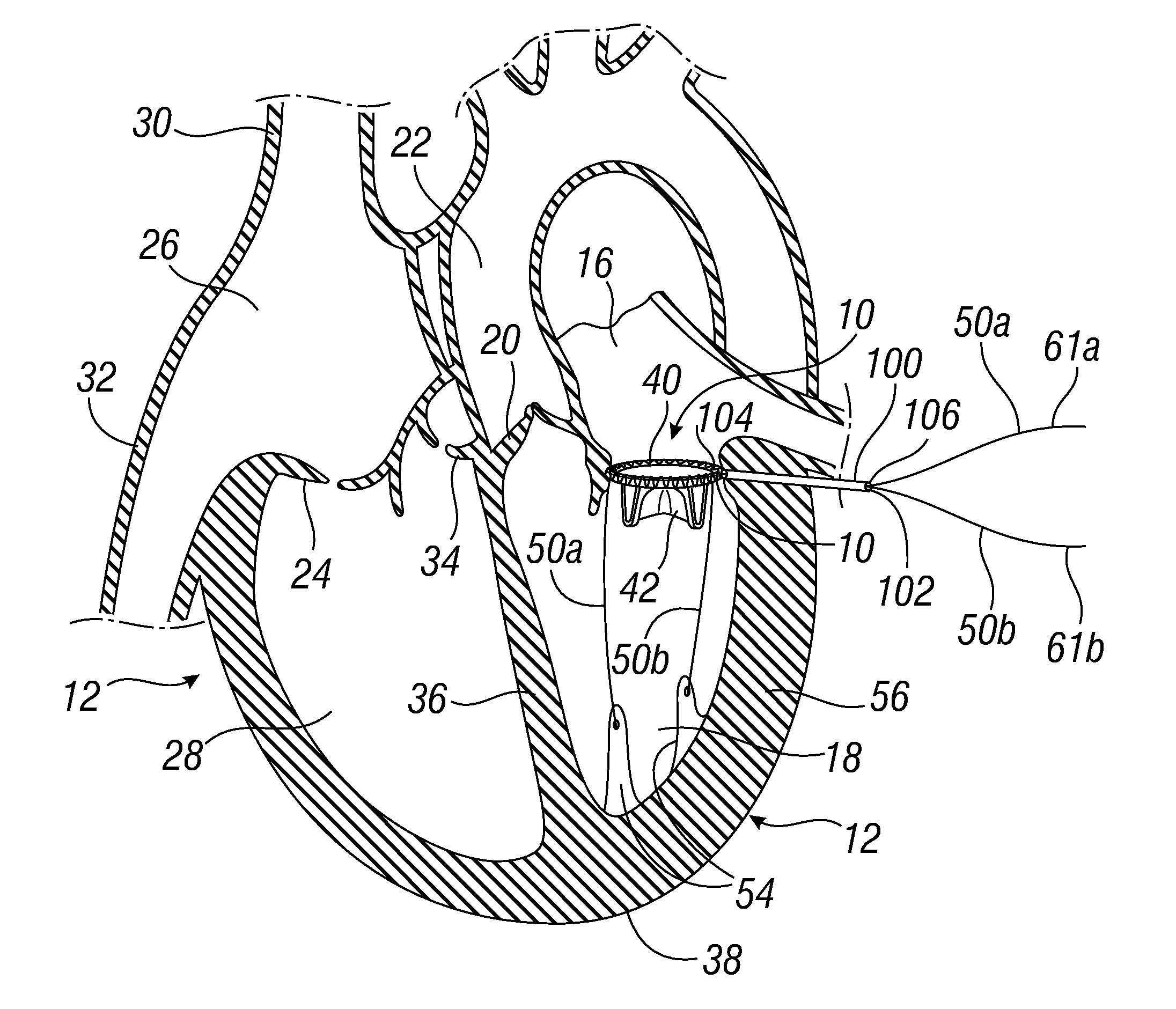
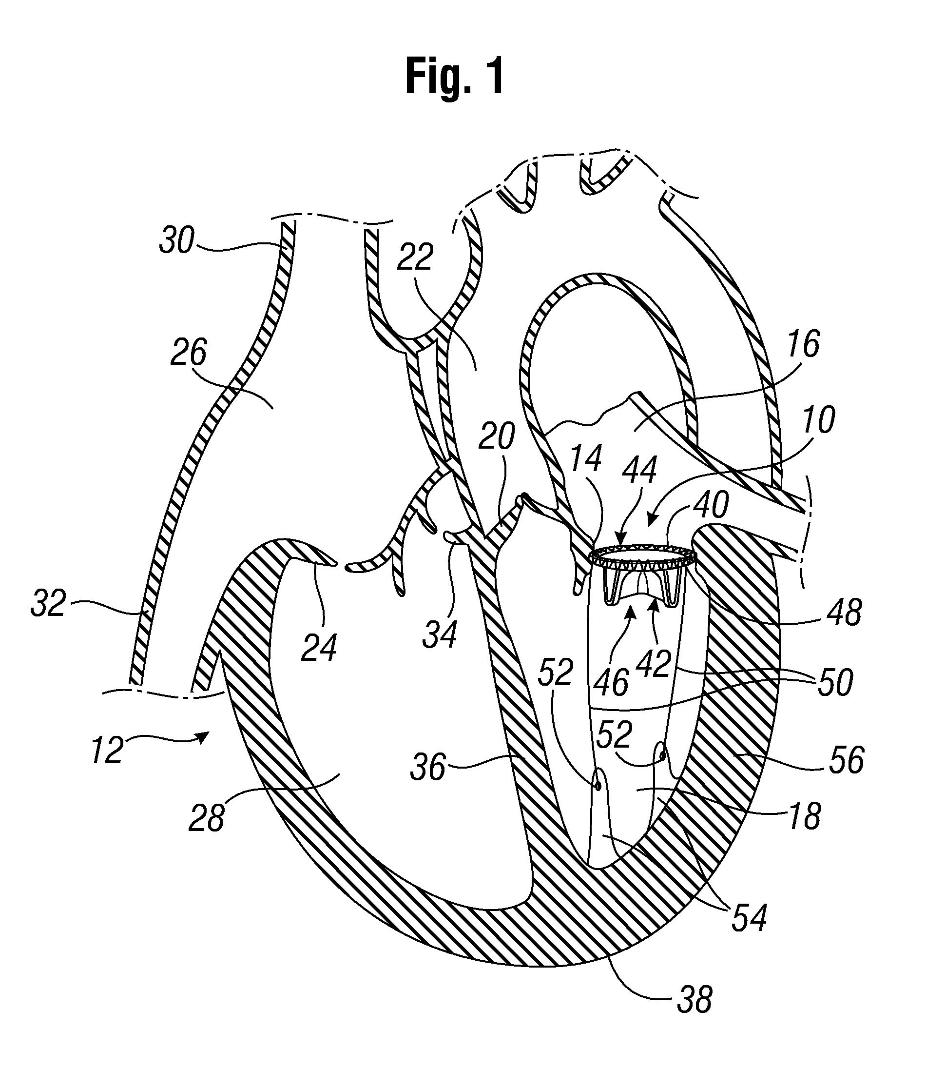
[0044]FIG. 1 shows a prosthetic mitral-valve assembly 10 deployed in a human heart 12, and more specifically implanted in the native mitral valve annulus 14. Note that the native mitral valve is not depicted, as its major structures (including the native valve leaflets and native chordae tendinae) are often removed to accommodate surgical implantation of the prosthetic mitral valve assembly 10. For purposes of background, the four-chambered heart 12 is explained further. On the left side of the heart 12, the native mitral valve annulus 14 is located between the left atrium 16 and left ventricle 18. The mitral valve annulus 14 is defined as the portion of tissue surrounding the mitral valve orifice. The left atrium 16 receives oxygenated blood from the pulmonary veins. The oxygenated blood that is collected in the left atrium 16 enters the left ventricle 18 through the mitral valve.

[0045]Contraction of the left ventricle 18 forces blood through the aortic valve 20 and into the aorta ...


PUM


Abstract

A prosthetic valve assembly and method of implanting same is disclosed. The prosthetic valve assembly includes a prosthetic valve formed by support frame and valve leaflets, with one or more tethers each having a first end secured to the support frame and the second end attached to, or configured for attachment to, to papillary muscles or other ventricular tissue. The tether is configured and positioned so as to avoid contact or other interference with movement of the valve leaflets, while at the same time providing a tethering action between the support frame and the ventricular tissue. The valve leaflets may be flexible (e.g., so-called tissue or synthetic leaflets) or mechanical.

Description

RELATED APPLICATIONS[0001]The present application claims priority under 35 U.S.C. §119 to U.S. Provisional Application Ser. No. 61 / 539,356, filed Sep. 26, 2011.FIELD OF THE INVENTION[0002]The current invention is directed to a prosthetic heart valve and a method for implanting such a prosthetic heart valve.BACKGROUND OF THE INVENTION[0003]The heart is a hollow muscular organ of a somewhat conical form; it lies between the lungs in the middle mediastinum and is enclosed in the pericardium. The heart rests obliquely in the chest behind the body of the sternum and adjoining parts of the rib cartilages, and typically projects farther into the left than into the right half of the thoracic cavity so that about one-third is situated on the right and two-thirds on the left of the median plane. The heart is subdivided by septa into right and left halves, and a constriction subdivides each half of the organ into two cavities, the upper cavity being called the atrium, the lower the ventricle. ...

Claims


Application Information

Patent Timeline
IPC IPC(8): A61F2/24
CPCA61B17/0401A61F2/2409A61F2/2412A61F2/2418A61F2/2457A61F2250/0007A61B2017/06176A61B2017/0417A61B2017/0437A61B2017/0441A61B2017/0464A61B2017/0496A61B17/0487
Inventor MIGLIAZZA, JOHN F.LAFRANCE, HUGUESCHEN, HARVEY H.OBA, TRAVIS ZENYO
Owner EDWARDS LIFESCIENCES CORP
Why Eureka
Try Eureka