Sensor element, method for manufacturing sensor element, sensor device, and electronic apparatus

a technology for sensors and electronic devices, applied in the direction of instruments, vibration measurement in solids, specific gravity measurement, etc., can solve the problems of deteriorating detection accuracy, difficult to make highly accurate adjustments of the amount of charge to be outputted from the pair of electrodes at the detection section, and difficult to obtain accurate dimensions of the tuning fork element according to the design. , to achieve the effect of improving the detection sensitivity of the sensor element, reducing the range of adjustment of the sensor output, and large electrod

Active Publication Date: 2013-04-04
SEIKO EPSON CORP
View PDF1 Cites 10 Cited by
  • Summary
  • Abstract
  • Description
  • Claims
  • Application Information

AI Technical Summary

Benefits of technology

[0022]In the sensor element in accordance with an aspect of the invention, a mass adjustment section may preferably be provided at a tip section of each of the first vibration arm and the second vibration arm. Accordingly, the resonance frequency of each of the first vibration arm and the second vibration arm can be adjusted independently. Therefore the resonance frequency of each of the first vibration arm and the second vibration arm can be made closer to the drive vibration frequency of the drive vibration arm, whereby the amplitude of vibration of the first vibration arm and the second vibration arm in response to the drive vibration of the drive vibration arm can be made greater, and the amount of charge to be generated at the first electrode and the second electrode can be made greater accordingly. As a result, the range of adjustment of the sensor output can be made greater.
[0023]In the sensor element in accordance with an aspect of the invention, it is preferred that the detection part may have a detection vibration arm that extends from the base part, and vibrates according to a physical quantity applied to the drive vibration arm, and the detection electrode may be provided on the detection vibration arm. Accordingly, the detection electrode can secure a large electrode area. Therefore, the detection sensitivity of the sensor element can be improved.
[0024]Another embodiment of the invention pertains to a method for manufacturing a sensor element that includes a base part; a drive vibration arm for vibrational drive that extends from the base part; a first vibration arm and a second vibration arm that extend from the base part and vibrate in response to vibrational drive of the drive vibration arm; a detection part including a detection electrode that outputs a signal according to a physical quantity applied to the drive vibration arm; a first electrode provided on the f

Problems solved by technology

However, it is difficult to obtain accurate dimensions of the tuning-fork element according to the design due to etching anisotropy of the substrate, variations in working process, and the like.
If a charge that is generated by the pair of electrodes at the detecting section, which may be caused by such

Method used


Image

  • Sensor element, method for manufacturing sensor element, sensor device, and electronic apparatus
  • Sensor element, method for manufacturing sensor element, sensor device, and electronic apparatus
  • Sensor element, method for manufacturing sensor element, sensor device, and electronic apparatus

Examples


first embodiment

+

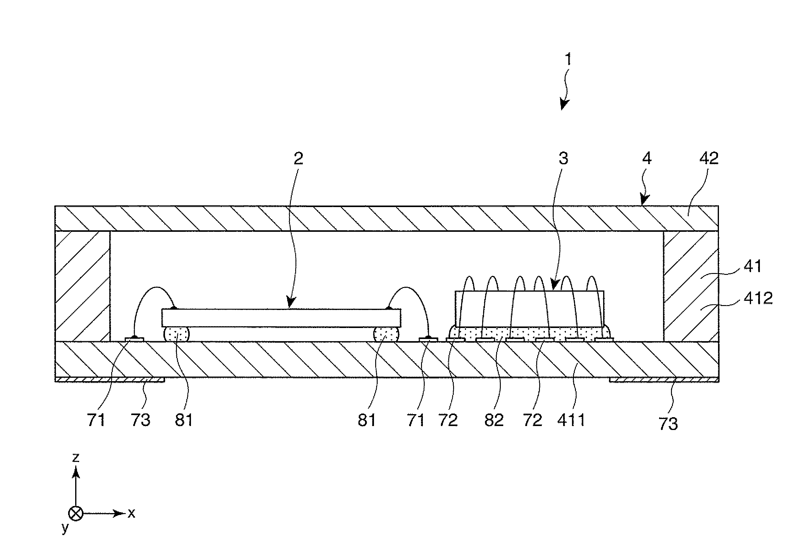
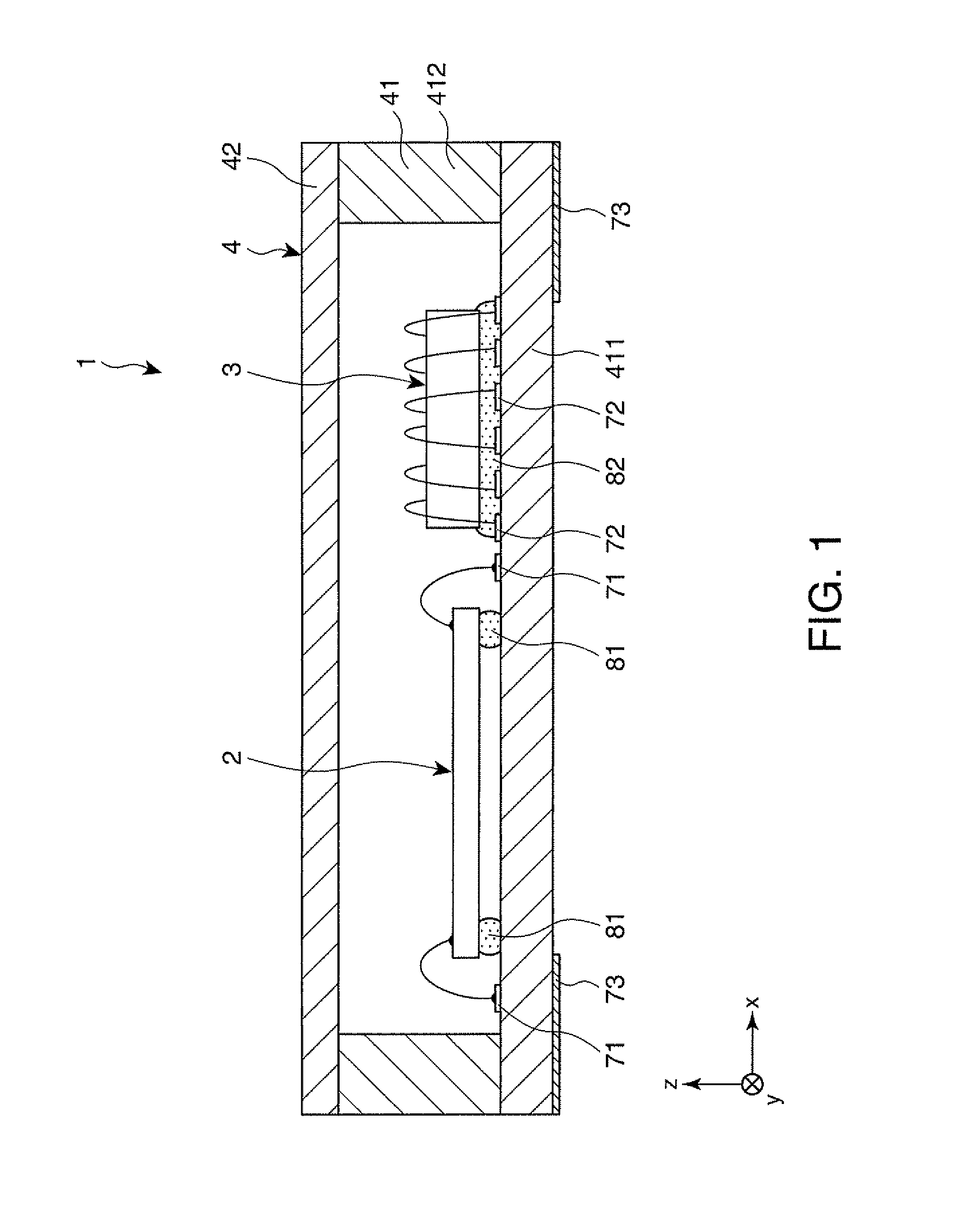
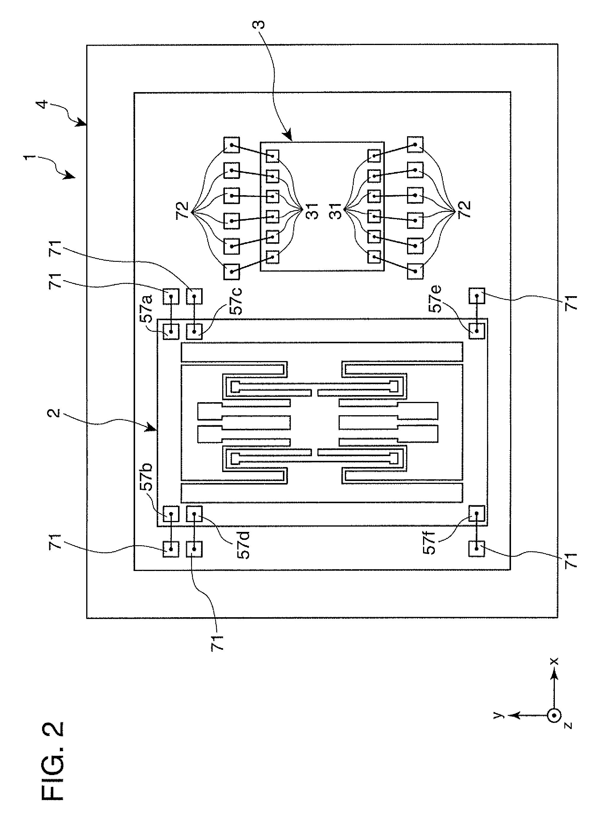
[0050]A first embodiment of the invention will be described. FIG. 1 is a schematic cross-sectional view briefly showing the composition of a sensor device (an electronic device) in accordance with the first embodiment of the invention. FIG. 2 is a plan view of the sensor device shown in FIG. 1. FIG. 3 is a plan view showing a sensor element provided in the sensor device shown in FIG. 1. FIG. 4A is an enlarged plan view of a drive vibration arm of the sensor element shown in FIG. 3, and FIG. 4B is a cross-sectional view of the drive vibration arm shown in FIG. 4A. FIG. 5A is an enlarged plan view of a detection vibration arm of the sensor element shown in FIG. 3, and FIG. 5B is a cross-sectional view of the detection vibration arm shown in FIG. 5A. FIG. 6A is an enlarged plan view of a first adjustment vibration arm of the sensor element shown in FIG. 3, and FIG. 6B is a cross-sectional view of the first adjustment vibration arm shown in FIG. 6A. FIG. 7A is an enlarged plan view of ...

second embodiment

[0119]Next, a second embodiment of the invention will be described. FIGS. 13A and 13B are enlarged plan views showing adjustment vibration arms of a sensor element in accordance with the second embodiment. The sensor element in accordance with the second embodiment is similar to the sensor element in accordance with the first embodiment described above, except that the wide parts at the tips of the first adjustment vibration arm and the second adjustment vibration arm and the mass adjusting films are omitted, and the first adjustment electrode and the second adjustment electrode have different shapes.

[0120]Note that, in the following description of the sensor element of the second embodiment, aspects different from the embodiment described above will be mainly described and description of similar aspects will be omitted. Also, in FIGS. 13A and 13B, the same signs are assigned to the same configurations as those of the embodiment described above. The sensor element in accordance with...

third embodiment

[0124]Next, a third embodiment of the invention will be described. FIG. 14 is an enlarged plan view showing an adjustment vibration arm of a sensor element in accordance with the third embodiment. The sensor element in accordance with the third embodiment is similar to the sensor element in accordance with the first embodiment described above, except that the wide parts at the tips of the first adjustment vibration arm and the second adjustment vibration arm and the mass adjusting films are omitted, and the first adjustment electrode and the second adjustment electrode have different shapes.

[0125]Note that, in the following description of the sensor element of the third embodiment, aspects different from the embodiments described above will be mainly described and description of similar aspects will be omitted. Also, in FIG. 14, the same signs are assigned to the same configurations as those of the embodiments described above. The sensor element in accordance with the third embodime...


PUM


Abstract

A sensor element includes a base part 21, drive vibration arms 221 and 222, adjustment vibration arms 241-244 that vibrate in response to drive vibration of the drive vibration arms 221 and 222, detection electrodes that output a charge according to a physical quantity applied to the drive vibration arms 221 and 222, first adjustment electrodes provided on the adjustment vibration arms 241 and 242 and electrically connected to the detection electrodes for outputting a charge in response to vibration of the adjustment vibration arms 241 and 242, and second adjustment electrodes provided on the adjustment vibration arms 243 and 244 and electrically connected to the detection electrodes for outputting a charge in a reverse polarity with respect to the first adjustment electrodes in response to vibration of the adjustment vibration arms 243 and 244.

Description

BACKGROUND[0001]1. Technical Field[0002]The present invention relates to sensor elements, methods for manufacturing a sensor element, sensor devices and electronic apparatuses.[0003]2. Related Art[0004]Angular velocity sensors (vibration gyro sensors) have been known (see, for example, JP-A-2008-14887 (Patent Document 1)) as sensor elements that are used for body control in vehicles, self-position detection of car navigation systems, vibration control and compensation systems (such as, shake compensation) for digital cameras, digital video cameras, and the like, and detect physical quantity, such as, angular velocity, acceleration and the like. For example, an angular velocity sensor described in Patent Document 1 has a tuning-fork element formed from two arms and a connection section that connects one ends of these two arms. Also, in the angular velocity sensor described in Patent Document 1, the tuning-fork element is formed from non-piezoelectric material, and each of the arms is...

Claims


Application Information

Patent Timeline
IPC IPC(8): G01H1/00H01L41/22H01L41/253H01L41/311
CPCG01C19/5621
Inventor ICHIKAWA, FUMIO
Owner SEIKO EPSON CORP
Why Eureka
Try Eureka