

Charged particle radiation device and soundproof cover
- Summary
- Abstract
- Description
- Claims
- Application Information
AI Technical Summary
Benefits of technology
Problems solved by technology
Method used
Image

Examples
embodiment 1
[0040]FIG. 7 is a diagram for explaining the embodiment of the present invention.
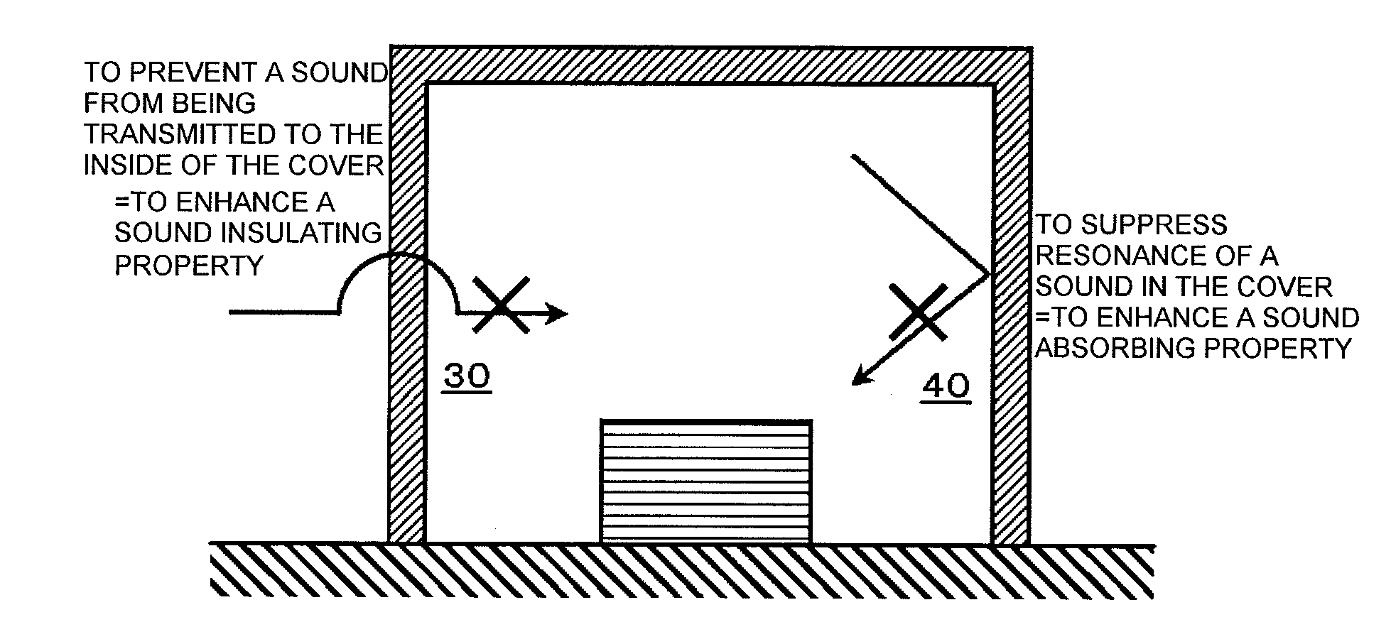
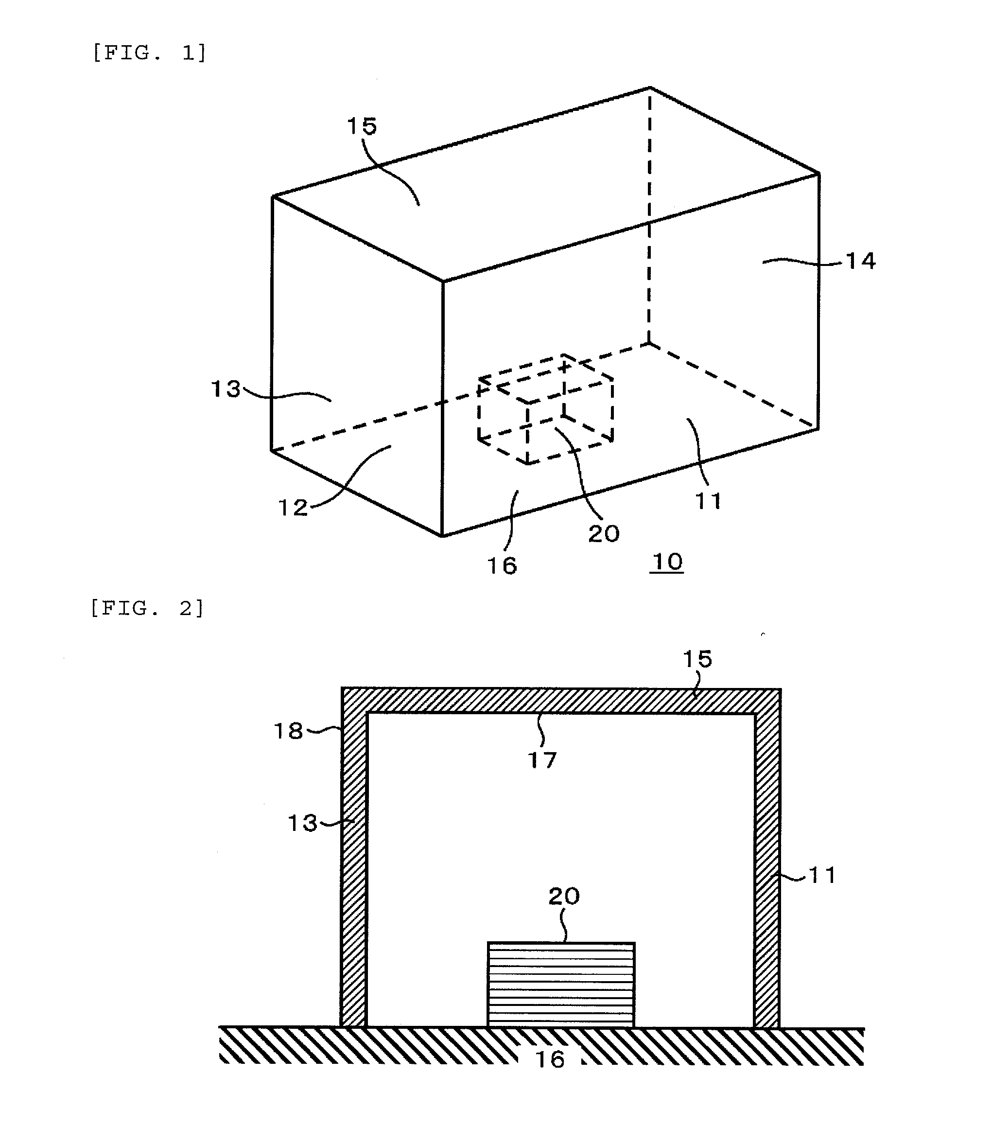
[0041]The device 20, on which sound insulation or vibration removal is intended to be performed, is surrounded with the sides 13 of the cover on four sides thereof, and the ceiling 15 of the cover is installed on the upper part of the sides 13 of the cover. Although the floor face 16 is not described in the example shown in FIG. 7, it is also possible to provide the floor face of the cover as shown in FIG. 1 if necessary. The space surrounded by these sides 13, the ceiling 15, and the floor or the floor face not shown, and containing the device 20 corresponds to the space from which the external vibration is removed. If no acoustic treatment is performed on the sides 13 of the cover, the side of the cover has a flat Structure in a macroscopic view, and in the case in which the space formed by the cover and the floor can be assumed to have a cuboid shape, there is generated the acoustic standing wave hav...
embodiment 2
[0052]Then, another example of the sound absorbing structure section 40 installed below the ceiling 15 of the cover in FIG. 7 will be explained.
[0053]In the present embodiment, as shown in FIG. 9, a perforated board 46 having a plurality of holes is disposed below the ceiling 15 of the cover so as to form a hollow section 46d in a space between the perforated board 46 and the ceiling 15. Although the mounting portion of the perforated board 46 is omitted in FIG. 9, the perforated board 46 can integrally be formed together with the ceiling 15 as a member having the hollow section 46d inside, or can be formed separately from the ceiling and fixed to the sidewalls. Further, it is also possible for the perforated board 46 to be attached to the ceiling via support members as described later. It should be noted that in view of the use in a clean room, it is necessary to use the material with a low dusting property for the perforated board 46 and the mounting portion. The design dimensions...
embodiment 3
[0056]Then, still another example of the sound absorbing structure section 40 installed below the ceiling 15 of the cover in FIG. 7 will be explained.
[0057]As shown in FIG. 11, partition walls 46f are formed on the inside surface of the ceiling 15, namely the surface on the side facing the device 20, to thereby form a plurality of cells 46e. The perforated board 46 having a plurality of holes is mounted on the lower surfaces of the cells, namely the surfaces on the side facing the device 20, and a perforated board sound absorbing unit 47 is formed by combining these components. The plurality of cells 46e corresponds to the hollow section of the sound absorbing section described above, and exerts the sound absorption effect. Similarly to the embodiments described above, those having a low dusting property need to be used as the members constituting the perforated board sound absorbing unit 47, taking the use in a clean room into consideration.
[0058]The perforated board sound absorbin...
PUM
 Abstract
Description
Claims
Application Information