Feed forward controlled voltage to current source for LED driver

a technology of current source and led driver, which is applied in the direction of dc-ac conversion without reversal, process and machine control, instruments, etc., can solve the problems of poor compatibility with phase controlled dimmers, poor power factor, and negative resistance inputs which are prone to oscillations, so as to minimize the dimming problem and efficiently drive the led

Inactive Publication Date: 2013-04-04
TEXAS INSTR INC
View PDF11 Cites 35 Cited by
  • Summary
  • Abstract
  • Description
  • Claims
  • Application Information

AI Technical Summary

Benefits of technology

[0006]It is a general object of the invention to provide for efficiently driving an LED and minimizing the dimming problem.

Problems solved by technology

However, the circuit suffers from disadvantages, including poor power factor when operated from an AC input, a negative resistance input which is prone to oscillations in the presence of EMI filters, and poor compatibility with phase controlled dimmers.
As the voltage applied to the LED is reduced, the circuit attempts to maintain the current through the LED constant, thus interfering with the dimming.
This involves relatively complex circuitry.
A common problem in lighting is the variation in light intensity caused by voltage changes.
For example, incandescent light bulbs suffer from a disadvantage that their light output varies widely when their operating voltage changes.
This further exacerbates the flicker problem.

Method used


Image

  • Feed forward controlled voltage to current source for LED driver
  • Feed forward controlled voltage to current source for LED driver
  • Feed forward controlled voltage to current source for LED driver

Examples


Embodiment Construction

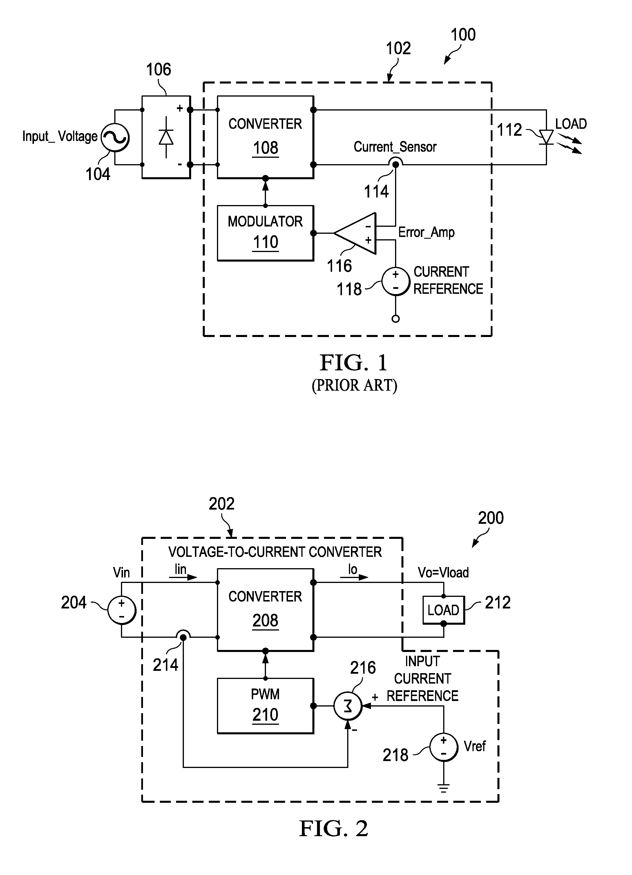
[0027]An aspect of the present invention is shown generally in FIG. 2 as 200. In FIG. 2, a DC input 204 is shown instead of of the AC input 104, shown in FIG. 1. The DC input can be an AC source coupled to a DC rectifier, such as a full wave rectifier 106, shown in FIG. 1, for example. The DC input voltage 204 is applied to a DC to DC converter 208 of LED driver circuit 200. The converter can utilize any converter topology, including isolated and nonisolated converters, and any control algorithm for controlling the input current. A current sensor 214 is placed in series between the negative input to the converter and the negative output of the power source. The output of converter 208 is connected to a load 212, which may be an LED or LED string, for example. The load could also be a DC to AC converter operating an AC load, such as a flourescent tube, for example. The converter may be controlled by a pulse width modulation (PWM) modulator circuit 210 which receives the output of an ...


PUM


Abstract

A DC to DC converter receives a DC input voltage and generates an output DC voltage. A current sensor measures a DC input current. A control circuit is coupled to the current sensor for controlling the DC to DC converter to have a constant DC input current.

Description

CROSS REFERENCE TO RELATED APPLICATIONS[0001]This patent application claims priority from U.S. Provisional Application No. 61 / 528,619, filed Aug. 29, 2011 which is incorporated herein by reference in its entirety.FIELD OF THE INVENTION[0002]The invention relates to a voltage to current converter having a constant input current and more specifically to a voltage to current converter having a constant input current for driving an LED.BACKGROUND OF THE INVENTION[0003]LEDs have become the technology of choice for lighting products due to their high efficiency, low cost, compact size, rugged design and very long life. Unlike more conventional lighting technology, such as incandescent bulbs, fluorescent tubes and compact fluorescent lamps (CFLs), LEDs are current driven devices. Their light output is specified at a current through the LED 112. The voltage drop across an LED or LED string may vary from batch to batch by as much as 15 percent. Accordingly, it is common to drive an LED or LE...

Claims


Application Information

Patent Timeline
Patent Type & Authority Applications(United States)
IPC IPC(8): G05F1/46H02M7/44H05B37/02H05B44/00
CPCH05B33/0815H05B33/0824G05F1/468H05B37/02Y02B70/126H02M1/4225H02M3/156Y02B20/347H02M7/44H05B45/44Y02B20/30Y02B70/10H05B47/10H05B45/38H02M1/0009H02M1/08H02M1/44H02M3/04
Inventor COHEN, ISAAC
Owner TEXAS INSTR INC
Why Eureka
Try Eureka