Automated tightening shoe

a shoe and automatic technology, applied in the field of shoes, can solve the problems of pain or unduly difficult pulling shoe laces tight and knotting, difficulty for ordinary wearers, elderly people suffering from arthritis, etc., and achieve the effect of convenient replacement, convenient loosing, and easy loosing upon demand

Active Publication Date: 2013-04-11
HANDS FREE ENTERPRISES LLC
View PDF48 Cites 76 Cited by
  • Summary
  • Abstract
  • Description
  • Claims
  • Application Information

AI Technical Summary

Benefits of technology

[0018]An automated tightening shoe that tightens snugly around the wearer's foot without use of the wearer's hands, and that can also be loosened easily upon demand without use of the wearer's hands is provided by this invention. The automated tightening shoe contains a sole and an integral body member or shoe upper constructed of any suitable material. The shoe upper includes a toe, a heel, a tongue, and medial and lateral sidewall portions. A unitary lace is provided for engaging a series of eyelets in a reinforced lacing pad along the periphery of the medial and lateral uppers. This lace is pulled by the automated tightening mechanism in a crisscrossed fashion across the tongue to draw the medial and lateral shoe uppers around the wearer's foot and snugly against the tongue on top of the wearer's instep. This automated tightening mechanism assembly is preferably located within a chamber contained within the shoe sole, and comprises a rotatable axle for winding the shoe lace. A roller wheel is attached to the axle that extends partially from the rear sole of the shoe, so that the wearer can rotate the roller wheel on the ground or floor to bias the axle of the automated tightening mechanism in the tightening direction. A ratchet wheel having ratchet teeth also secured to the axle is successively engaged by a pawl at the distal end of a release lever to prevent the axle from counter-rotating. When the wearer engages the release lever preferably extending from the heel of the shoe, however, the pawl is pivoted out of engagement with the teeth of the ratchet wheel, so that the axle of the automated tightening mechanism can freely counter-rotate to release the shoe lace to its standby position, and allow the shoe lace to be loosened easily without the use of the wearer's hands. Moreover, the shoe lace should extend through the entire rotatable axle so that it can be readily replaced by threading a new lace attached thereto through the interior of the shoe uppers and into operative engagement with the rotatable axle of the automated tightening mechanism without access to the tightening mechanism positioned inside the shoe sole chamber required.
[0019]The automated tightening mechanism may contain a separate metal spring for biasing the pawl of the release lever into engagement with the teeth of the ratchet wheel when the wearer ceases to engage the release lever. This will prevent counter-rotation of the axle and loosening of the shoe lace. Alternatively, the release lever may have a deflection member integrally attached thereto to eliminate the need for the separate metal spring. This deflection member may extend laterally from an arm portion of the release lever, or back in substantially parallel overlap with the arm with a gap between the deflection member and the arm. When the release lever is actuated by the wearer to disengage the pawl from the teeth of the ratchet wheel to allow the shoe laces to loosen, the deflection member will be deflected with respect to the arm by its abutment against an interior surface of the housing containing the automated tightening mechanism assembly. When the wearer no longer actuates the release lever, the deflection member will automatically push off the interior housing surface to return substantially to its original shape and position, and the release lever to its original position with the pawl engaging once again the tooth of the ratchet wheel. In this manner, the release lever contains an internal “spring-back” function for operating the automated tightening mechanism without any separate metal spring.

Problems solved by technology

This can be a hassle for the ordinary wearer.
Moreover, young children may not know how to tie a knot in the shoe lace, thereby requiring assistance from an attentive parent or caregiver.
Furthermore, elderly people suffering from arthritis may find it painful or unduly challenging to pull shoe laces tight and tie knots in order to secure shoes to their feet,
These mechanisms are complicated in their number of parts needed to operate in unison.
However, such tension lever or push plate may not have constant pressure applied to it by the foot, which will result in loosening of the tightening cable or strap.
Moreover, the wearer may find it uncomfortable to step on the tension lever or push plate throughout the day.
But, such a battery-operated device can suffer from short circuits, or subject the wearer to a shock in a wet environment.
But, such Velcro closures can frequently become disconnected when too much stress is applied by the foot.
Moreover, Velcro closures can become worn relatively quickly, losing their capacity to close securely.
Furthermore, many wearers find Velcro straps to be aesthetically ugly on footwear.
However, none of the automated tightening systems heretofore devised has been entirely successful or satisfactory.
Major shortcomings of the automated tightening systems of the prior art are that they fail to tighten the shoe from both sides so that it conforms snugly to the wearer's foot, and that they lack any provision for quickly loosening the shoe when it is desired to remove the shoe from the wearer's foot.
Moreover, they frequently suffer from: (1) complexity, in that they involve numerous parts; (2) the inclusion of expensive parts, such as small electric motors; (3) the use of parts needing periodic replacement, e.g. a battery; or (4) the presence of parts requiring frequent maintenance, These aspects, as well as others not specifically mentioned, indicate that considerable improvement is needed in order to attain an automated tightening shoe that is completely successful and satisfactory.
However, because the laces are physically secured to the tightening mechanism contained within a chamber of the shoe sole, they cannot be replaced should they fray or break.
This shortens the useful life of the shoe product.
Such a popular shoe is sold under the brand Wheelies® However, this type of convertible roller skating shoe does not contain an automated tightening mechanism, let alone use the roller wheel to actuate such a mechanism.

Method used


Image

  • Automated tightening shoe
  • Automated tightening shoe
  • Automated tightening shoe

Examples


embodiment 233

[0072]FIGS. 13-15 show an alternative embodiment 233 of first end shaft 232 or second end shaft 234. It is similar in design and construction to the end shaft depicted in FIGS. 7, 8, and 11 with the exception of an additional containment disk wall 288 molded between inner cylindrical shoulder 264 and outer cylindrical boss 266. This containment disk wall has a diameter that is larger than the diameter of the inner cylindrical shoulder. In this manner, containment disk wall 288 and disk portion 260 of end shaft 233 cooperate to define a region 289 for winding and unwinding lace 136 or engagement cable 196, while the containment disk wall 288 prevents undue lateral migration of the lace 136 or engagement cable 196. This helps to prevent the lace or engagement cable from getting tangled in the axle assembly 224, and impeding its rotational movement.

[0073]FIG. 9 shows actuator wheel 212 secured to wheel shaft 230. Actuator wheel 212, as shown more clearly in FIG. 8, contains a channel 2...

case 220

[0081]Forward case 220 as shown in FIGS. 7 and 17 is preferably molded from RTP 301 polycarbonate glass fiber 10% or functionally equivalent material. It has an outer surface wall 300 and base wall 302. This base wall 302 should be fiat so that it provides an ideal way to fasten the housing assembly 220 and 222 containing the automated tightening mechanism 210 to the chamber bottom 202, such as by means of adhesive. This housing contains the various parts of the automated tightening mechanism while allowing entry and exit of the shoe lace 136, rotation of the axle assembly 224 in both the tightening and loosening direction, and external operation of the actuator wheel 212 and release lever 214 extending therefrom.

[0082]FIG. 17 shows the interior of forward case 220. It features cut-away portion 304 for accommodating, actuator wheel 212. Actuator wheel 212 must be capable of rotating freely without rubbing against forward case 220. Shoulder surfaces 306 and 308 defined by indents 307...

embodiment 210

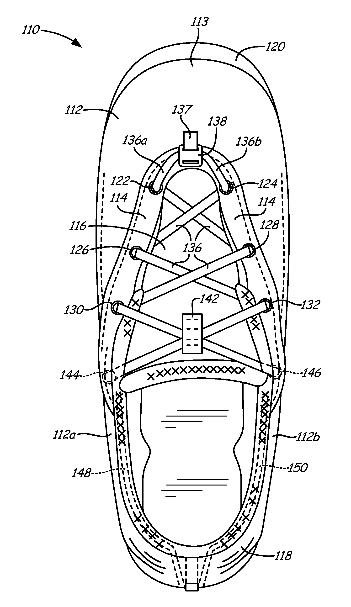
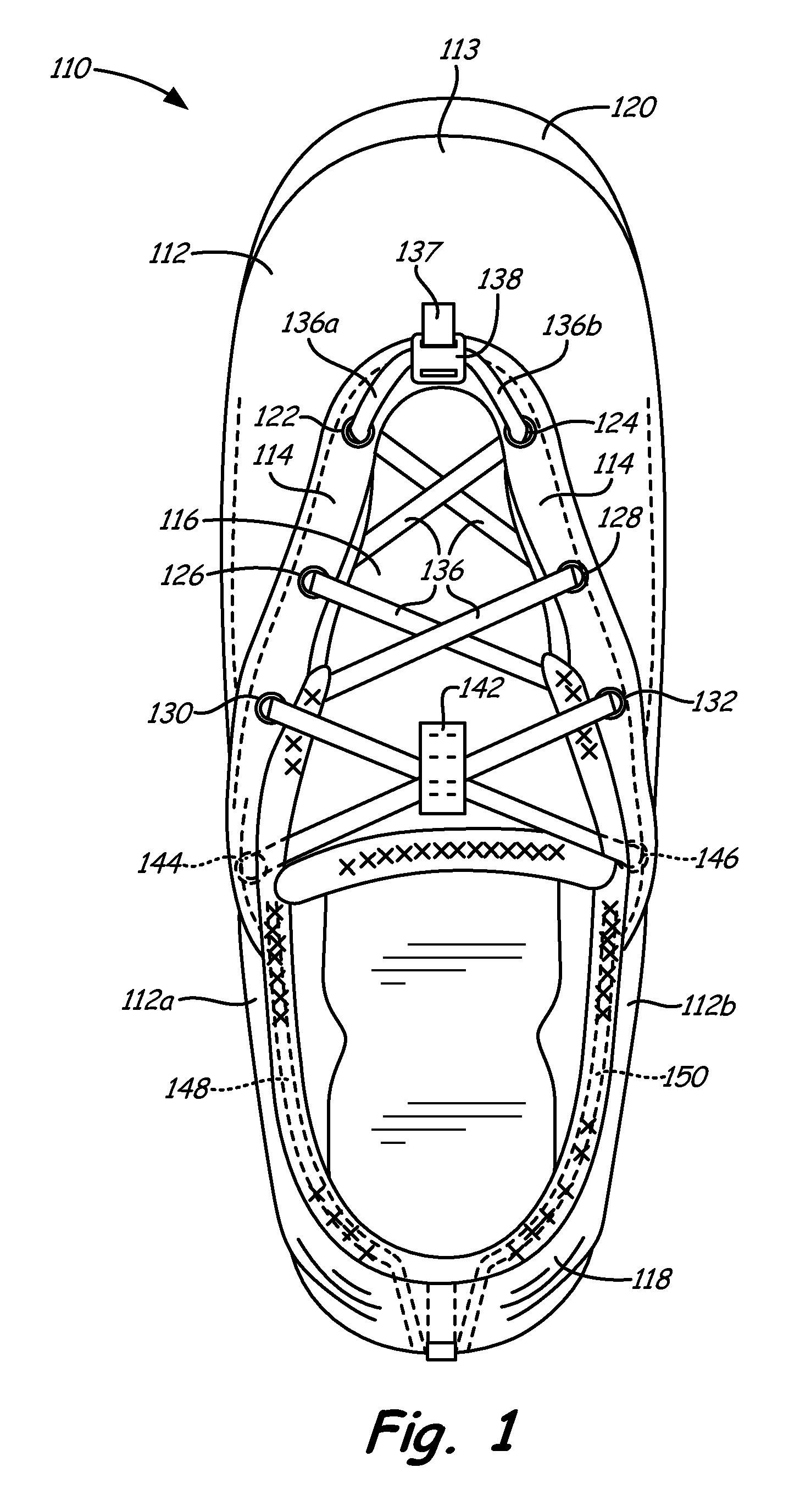
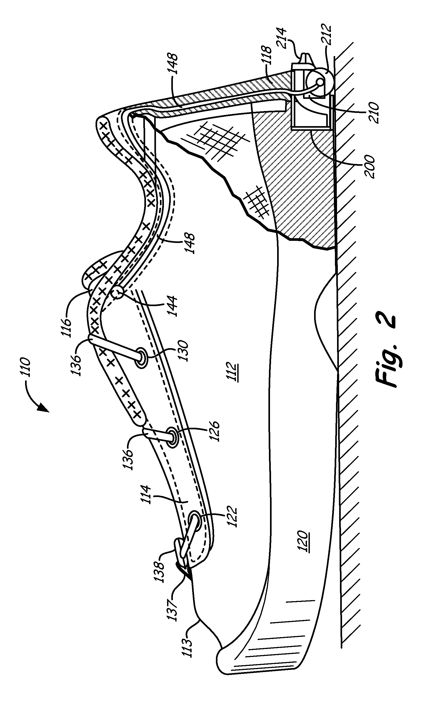
[0092]The automated tightening mechanism 210 of the present invention is simpler in design than other devices known within the industry. Thus, there are fewer parts to assemble during shoe manufacture and to break down during usage of the shoe. Another substantial advantage of the automated tightening mechanism embodiment 210 of the present invention is that shoe lace 136 and their associated guide tubes may be threaded down the heel portion of the shoe upper, instead of diagonally through the medial and lateral uppers. This feature greatly simplifies manufacture of shoe 110. Moreover, by locating automated tightening mechanism 210 closer to the heel within shoe sole 120, a smaller housing chamber 200 may be used, and the unit may more easily be inserted and glued into a smaller recess within the shoe sole during manufacture.

[0093]Another significant advantage of the automated tightening mechanism 210 of the present invention is the fact that a single shoe lace 136 is used to tighte...


PUM


Abstract

An automated tightening shoe with a single crisscrossed laces or closure panel and a tightening mechanism which operates in one direction to cause automatic tightening of the crisscrossed laces or closure panel to tighten the shoe about a wearer's foot, and which can be released easily so that the shoe can be removed from the wearer's foot. An actuating wheel partially projecting from the rear sole of the shoe provides a convenient and reliable actuating means for movement of the automated tightening mechanism in the tightening direction.

Description

CROSS-REFERENCE TO RELATED APPLICATION[0001]This application is a continuation-in-part of U.S. Ser. No. 13 / 199,078 filed on Aug. 18, 2011, which is hereby incorporated by reference.FIELD OF THE INVENTION[0002]The present invention pertains to a shoe and, more particularly, to an automated tightening shoe. The shoe is provided with an automated tightening system, including a tightening mechanism which operates in one direction to cause automatic tightening of the shoe about a wearer's foot, and which can be released easily so that the shoe can be readily removed from the wearer's foot. The invention is chiefly concerned with an automated tightening shoe of the sport or athletic shoe variety, but the principles of the invention are applicable to shoes of many other types and styles.BACKGROUND OF THE INVENTION[0003]Footwear, including shoes and boots, are an important article of apparel. They protect the foot and provide necessary support, while the wearer stands, walks, or runs. They ...

Claims


Application Information

Patent Timeline
Patent Type & Authority Applications(United States)
IPC IPC(8): A43C11/00
CPCA43C1/00A43C11/165A43C11/00A43B11/00
Inventor JOHNSON, GREGORY G.TOMBERS, ARTHUR J.
Owner HANDS FREE ENTERPRISES LLC
Why Eureka
Try Eureka