Ventilation systems and methods

a ventilation system and ventilation system technology, applied in the direction of valves, respirators, mechanical equipment, etc., can solve the problems of inconvenient use, high cost, complicated use of full-featured machines, etc., and achieve the effect of inexpensive mass production

Active Publication Date: 2013-04-11
THE BOARD OF TRUSTEES OF THE LELAND STANFORD JUNIOR UNIV
View PDF19 Cites 41 Cited by
  • Summary
  • Abstract
  • Description
  • Claims
  • Application Information

AI Technical Summary

Benefits of technology

[0008]The present invention is directed generally to ventilators and systems and methods of ventilation for humans and other animals. For example, the ventilators described herein may be built with minimal resources, e.g., allowing for inexpensive mass production.

Problems solved by technology

Currently marketed ventilators range from costly, sophisticated machines to simple low cost transport devices.
Currently marketed full-featured machines are prohibitively expensive, fragile, and overly complex for use by less skilled personnel.
Portability and durability are limited and a constant power supply is required.
These features make full-featured machines unsuitable for use in field settings, rural areas, or in a large scale emergency situation such as a pandemic.
Although they are more portable than the full featured ventilators, transport ventilators are not appropriate for use in ARDS patients during a pandemic.
They often do not provide PEEP, have no spontaneous assist mode and are not approved for critical care use.
Inefficient use of compressed air and electricity also make them ill-suited for low-resource environments and developing nations.
When considered on a global scale, the disparity in pandemic resources between wealthy and impoverished nations is alarming.
With the majority of the world's vaccine supply already purchased by wealthy nations, coverage in developing nations may be inadequate.
Many countries already face an extreme shortage of ventilators, even in the absence of a pandemic.

Method used


Image

  • Ventilation systems and methods
  • Ventilation systems and methods
  • Ventilation systems and methods

Examples


Embodiment Construction

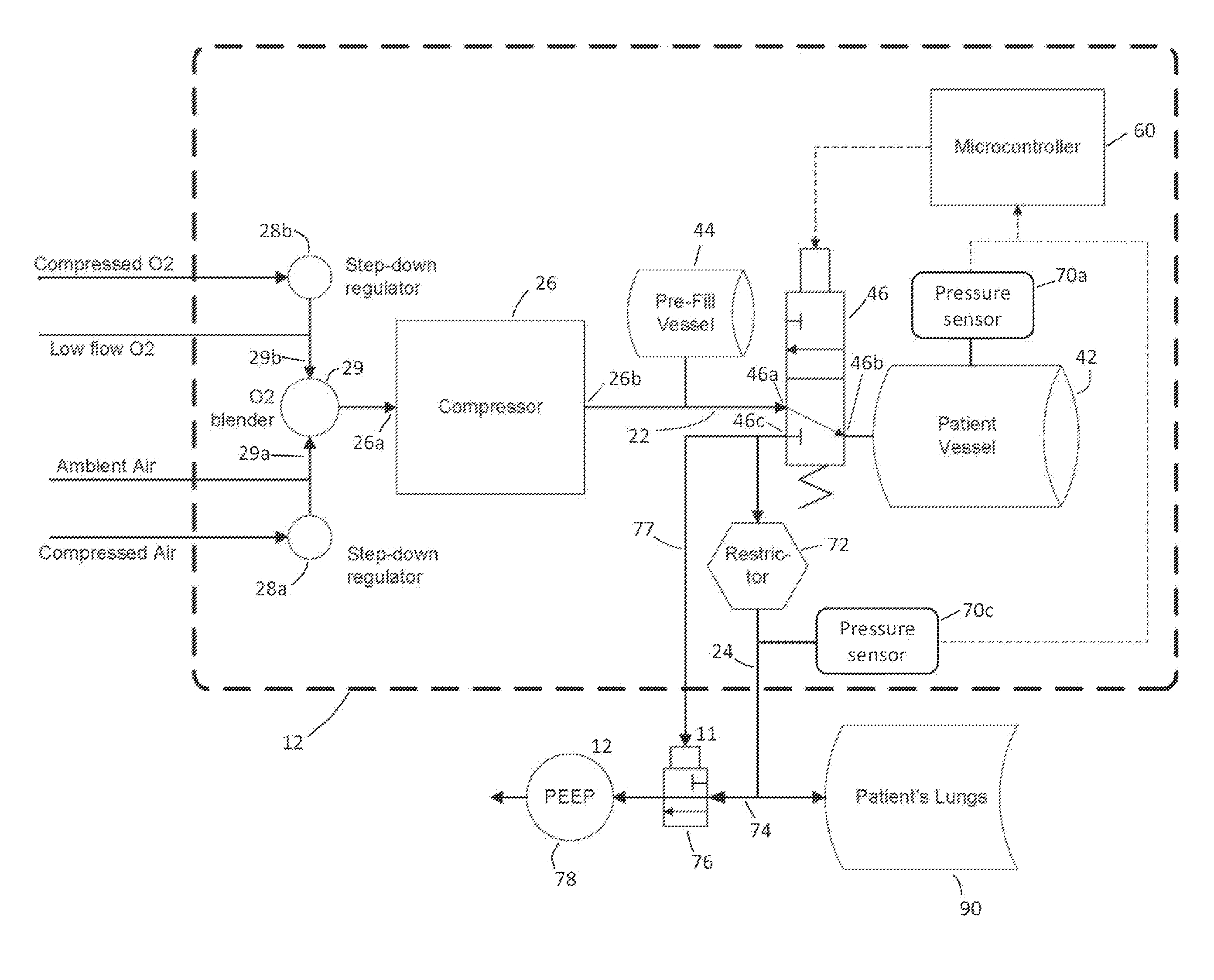
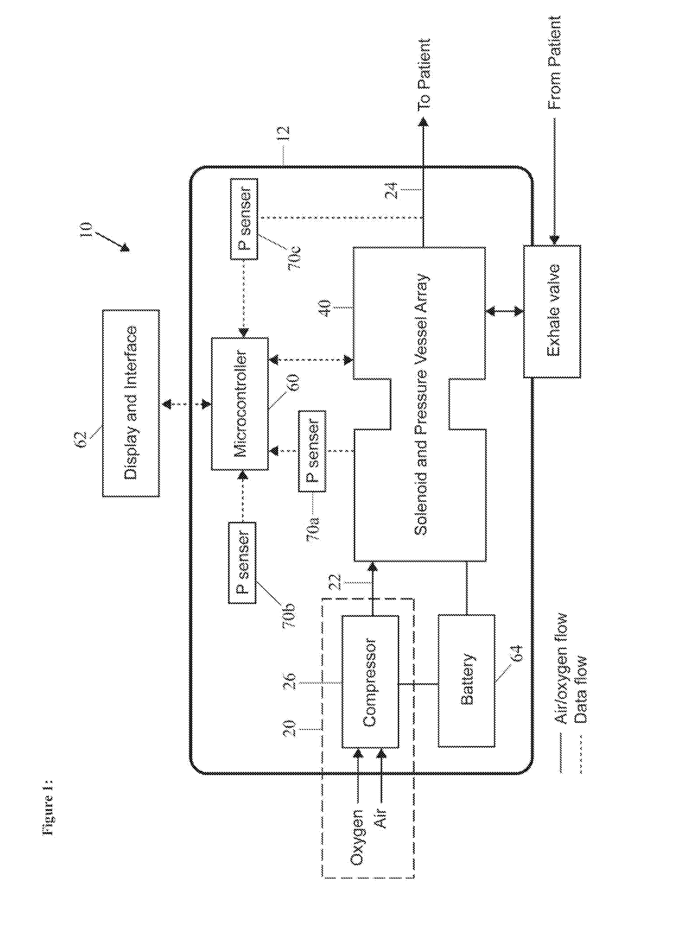
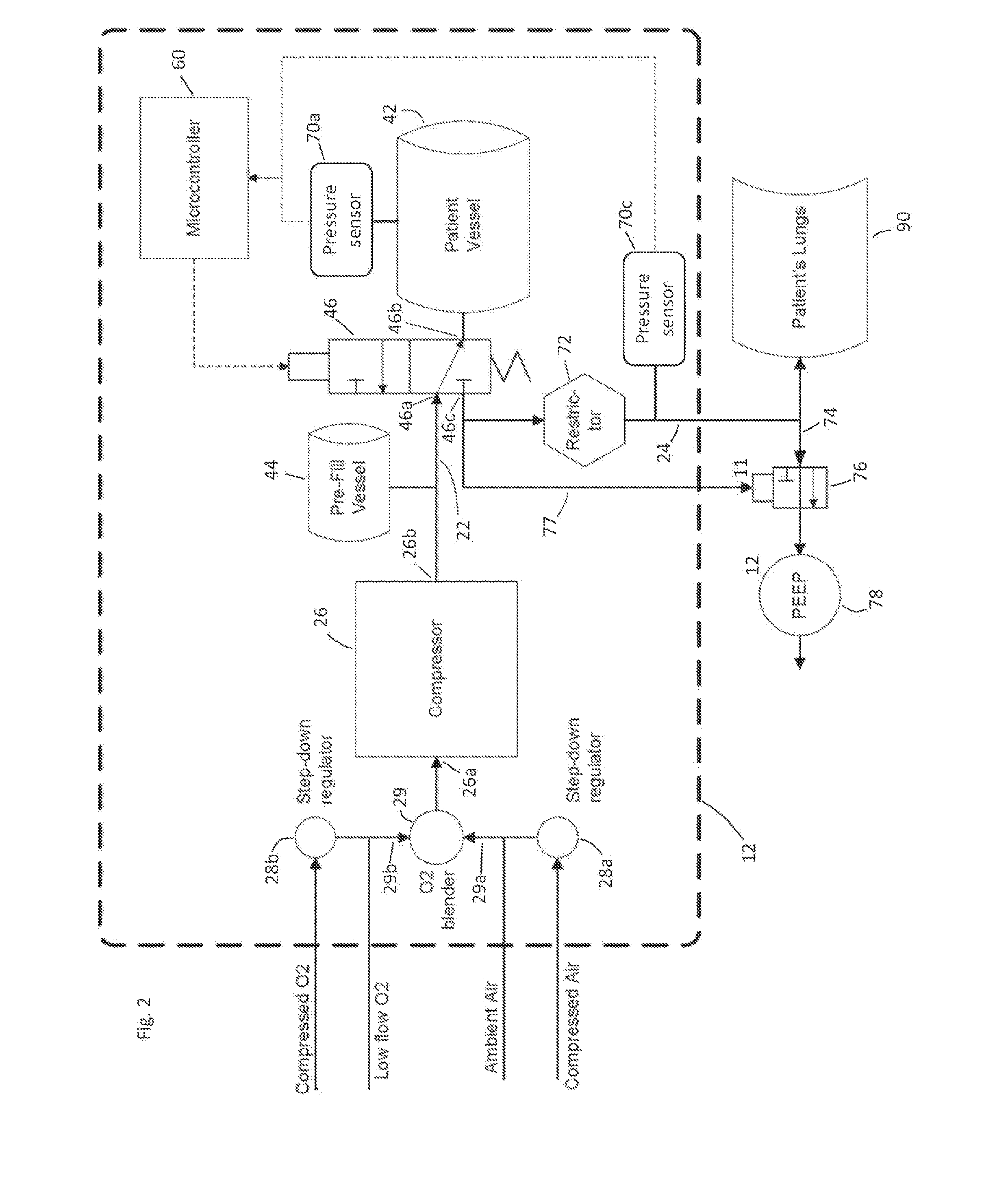
[0036]Turning to the drawings, FIG. 1 shows an exemplary embodiment of a ventilator system 10, e.g., a portable ventilator that includes a relatively light-weight housing 12 carrying various components of the system 10. Generally, the system 10 includes one or more source lines 22 that receive gas from one or more sources of pressurized gas 20 and an array 40 including one or more storage vessels and / or valves communicating with the gas source(s) 20 via the source line(s) 22 and / or communicating with an inhalation line 24, e.g., for delivering gas to a patient, as described further below. For example, as shown in FIG. 2, the array 40 may include a valve assembly 46 including one or more valves communicating with one or more storage vessels 42. The system 10 may also include one or more controllers 60 coupled to the array 40, e.g., for operating one or more valves of the array 40, to one or more sensors, e.g., pressure sensors 70 that provide pressure data from one or more components...


PUM


Abstract

A ventilator includes a compressor, a storage vessel, a valve assembly communicating with the compressor, the storage vessel, and an inhalation line. A controller directs the valve assembly between a storage configuration where ventilation gas is delivered from the compressor into the storage vessel, and a delivery configuration where ventilation gas is delivered from the storage vessel to the inhalation line. The controller is coupled to a pressure sensor for detecting a first pressure within the storage vessel when the valve assembly is directed to the delivery configuration, and detecting subsequent pressure while ventilation gas is delivered from the storage vessel to the inhalation line, the controller determining the volume of ventilation gas delivered to the patient based at least in part on the difference between the first pressure and the subsequent pressure.

Description

RELATED APPLICATION DATA[0001]The present application is a continuation of co-pending International Application No. PCT / US2010 / 056428, filed Nov. 11, 2012, which claims benefit of U.S. provisional application Ser. No. 61 / 260,296, filed Nov. 11, 2009, the entire disclosures of which are expressly incorporated by reference herein.FIELD OF THE INVENTION[0002]The present invention relates generally to ventilators and systems and methods of ventilation for humans and other animals. More particularly, the present invention relates to ventilators that may be built with minimal resources, allowing for inexpensive mass production.BACKGROUND[0003]Surge capacity mechanical ventilation during an influenza pandemic requires devices capable of positive pressure ventilation (“PPV”) and delivery of positive end expiratory pressure (“PEEP”). The duration of disease may last from days to weeks, and mechanical ventilation may be required for greater than one week. One of the most dangerous results of ...

Claims


Application Information

Patent Timeline
Patent Type & Authority Applications(United States)
IPC IPC(8): A61M16/20
CPCA61M16/00A61M16/12A61M2016/0021A61M2205/3351A61M2205/3358A61M16/205A61M2205/8206A61M16/208A61M16/0063A61M16/204A61M2205/502A61M16/107A61M16/024
Inventor CALLAGHAN, MATTHEW JOHNBISHOP, WILLIAMMILLER, LAWRENCE EDWARDFRYKMAN, PETERBRAHIC, FRANCOIS
Owner THE BOARD OF TRUSTEES OF THE LELAND STANFORD JUNIOR UNIV
Why Eureka
Try Eureka