Resin Mold, Production Method Thereof, and Use Thereof

a technology of resin film and release layer, applied in the field of resin film, can solve the problems of poor adhesion of oxide film to resin film, release layer shed, etc., and achieve the effect of inexpensive mass production and excellent releasability

Inactive Publication Date: 2013-05-30
SOKEN CHEM & ENG CO LTD
View PDF4 Cites 3 Cited by
  • Summary
  • Abstract
  • Description
  • Claims
  • Application Information

AI Technical Summary

Benefits of technology

[0039]The resin mold of the present invention has excellent releasability from the resin to be imprinted, and there is no shedding of mold release agent due to imprinting. Moreover, the imprinted resin has no transfer defects.
[0040]The resin mold of the present invention is mainly composed of resin, and thus inexpensive mass production is possible, and the resin mold is flexible.

Problems solved by technology

However, there has been a problem in that, when the release layer adheres poorly to the mold, the release layer is shed due to imprinting.
Resin molds are being used in recent years due to general versatility and cost.
However, since the resin mold and the resin to be imprinted are both resins, adhesion of the mold release agent is of a similar extent to both resins, and this results in a problem in that the release layer is transferred to the resin to be imprinted.
Although it is possible to prevent shedding of the release layer from the oxide layer by formation of a release layer with this oxide layer interposed between the release layer and the mold, adhesion of this oxide film to the resin film is not necessarily good.
Therefore, there is a problem in that, even when the release layer and the oxide film are integrated, there still may be transfer of the integrated release layer and oxide film to the surface of the imprinted resin film.

Method used


Image

  • Resin Mold, Production Method Thereof, and Use Thereof
  • Resin Mold, Production Method Thereof, and Use Thereof
  • Resin Mold, Production Method Thereof, and Use Thereof

Examples


example 1

(i) Preparation of Resin (PMMA Type) for the Resin Mold

[0144]95 parts by weight of methyl methacrylate (product name=LIGHT ESTER M, manufactured by Kyoeisha Chemical Co., Ltd.), 5 parts by weight of glycidyl methacrylate (product name=LIGHT ESTER G, manufactured by Kyoeisha Chemical Co., Ltd.), and 100 parts by weight of toluene were added to a flask equipped with a stirrer device, nitrogen gas feed tube, thermometer, and tubular refluxing condenser. Thereafter, while nitrogen gas was fed into the flask, the contents of the flask were heated to 80° C., 0.5 parts by weight of dimethyl 2,2′-azobis(2-methylpropionate) (product name=V-601, manufactured by Wako Pure Chemical Industries, Ltd.) as the initiator was added, and temperature was maintained at 80° C. for 8 hours. Thereafter, the flow of nitrogen gas was stopped, 100 parts by weight of toluene was added, and the reaction was stopped by lowering temperature to obtain the resin for the resin mold. Molecular weight of the obtained ...

example 2

[0153]Except for setting the added amount of 3-glycidoxypropyltrimethoxysilane in step (ii-a) of Example 1 to 10 parts by weight, a resin mold was produced in the same manner as Example 1. The obtained resin mold was used to perform photo-nanoimprinting in the same manner as that of Example 1.

[0154]Nanoimprinting results and the obtained resin mold for nanoimprinting are indicated in Table 1.

example 3

[0155]Except for setting the added amount of 3-glycidoxypropyltrimethoxysilane in step (ii-a) of Example 1 to 1 part by weight, a resin mold was produced in the same manner as Example 1. The obtained resin mold was used to perform photo-nanoimprinting in the same manner as that of Example 1.

[0156]Nanoimprinting results and the obtained resin mold for nanoimprinting are indicated in Table 1.


PUM

PropertyMeasurementUnit
sizesaaaaaaaaaa
thicknessaaaaaaaaaa
compatibilityaaaaaaaaaa

Abstract

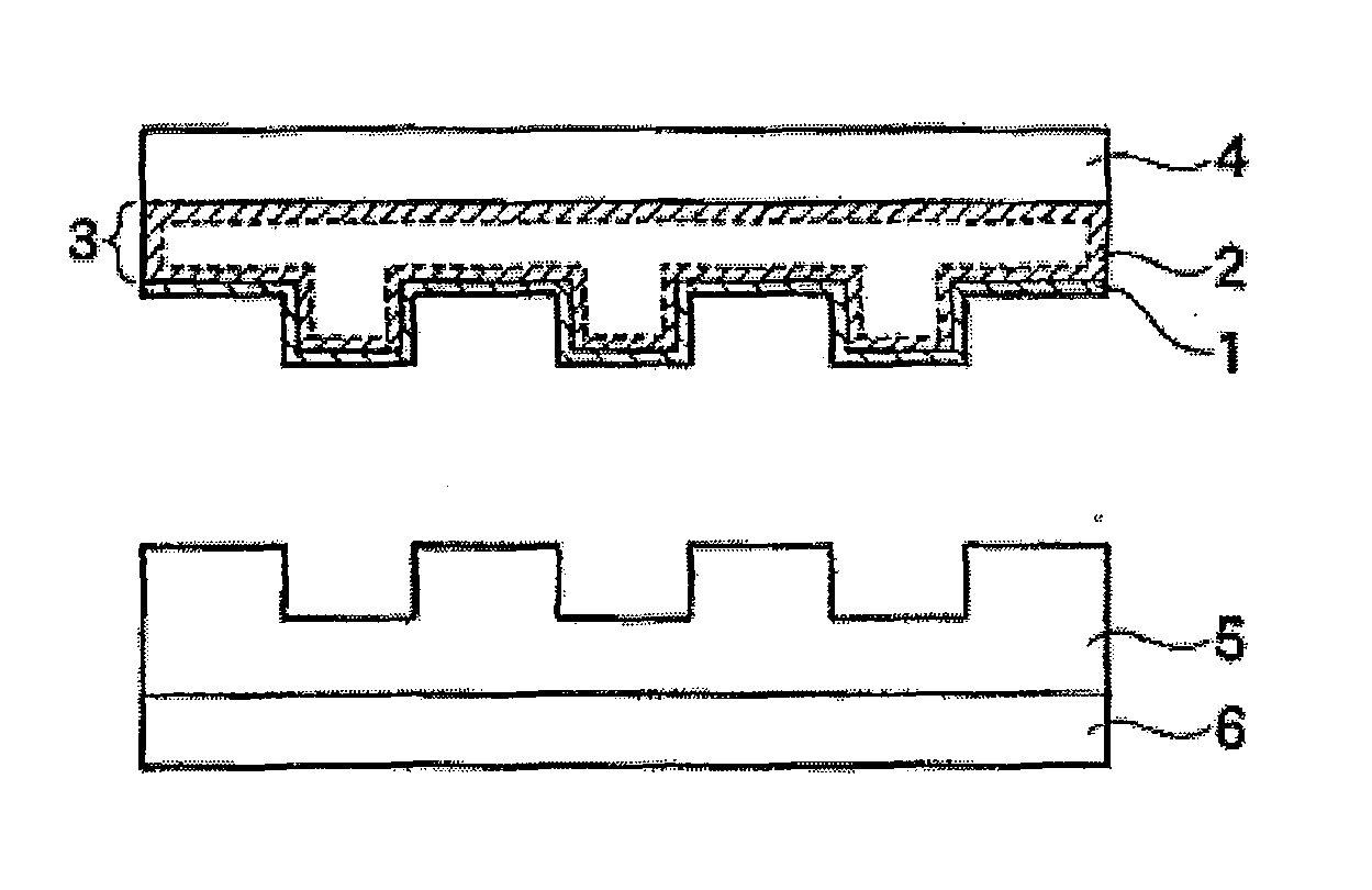
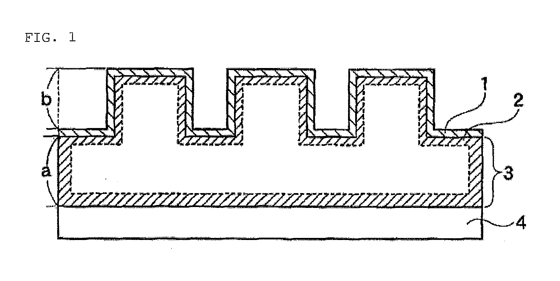
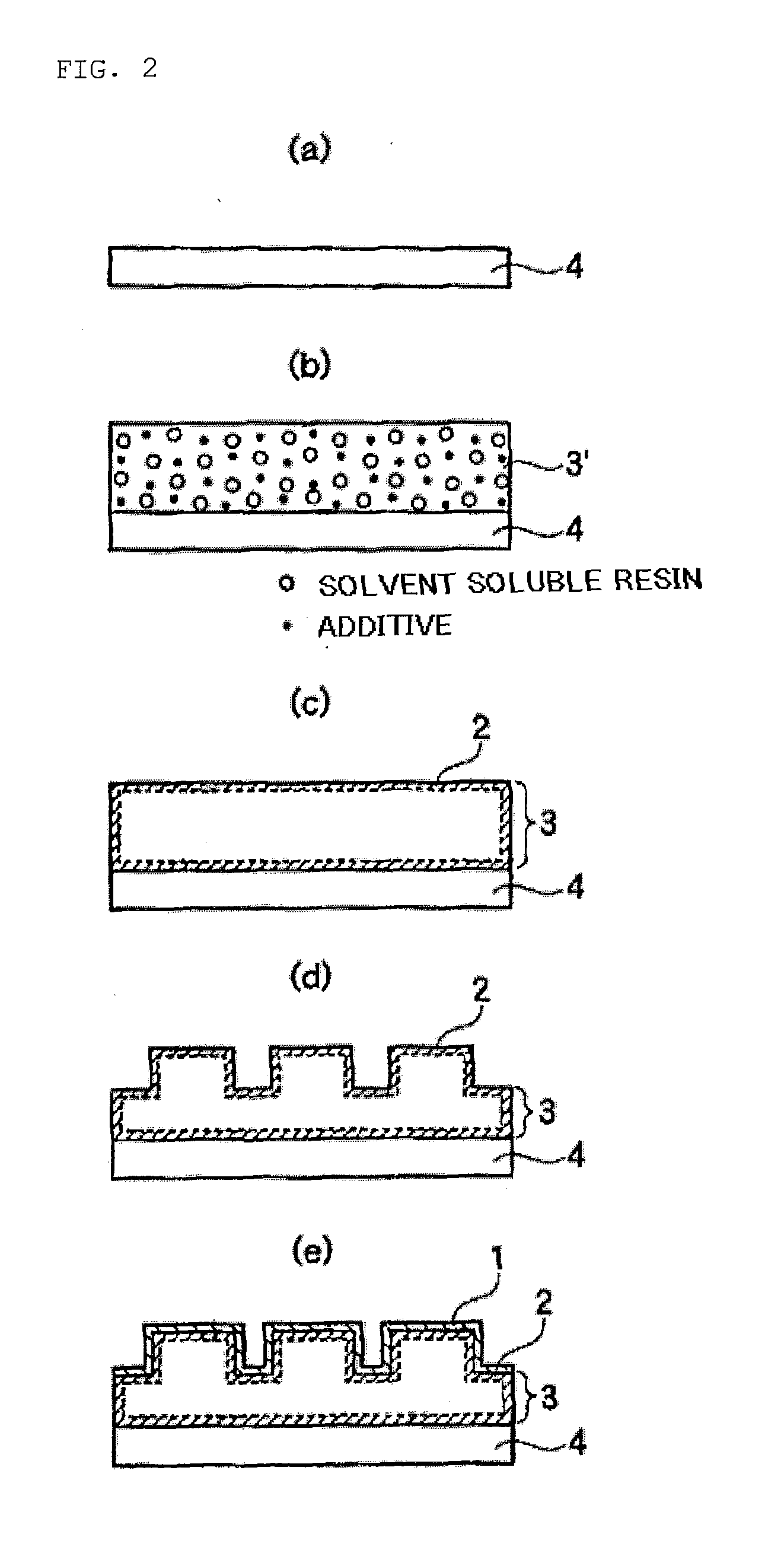
A resin mold includes a resin layer having a depressions and protrusions pattern formed in the surface thereof, and a release layer including a mold release agent and formed of uniform thickness on at least the depressions and protrusions pattern of the aforementioned resin layer. The aforementioned resin layer has a solvent soluble resin, and an additive that has bleeding ability with respect to the solvent soluble resin, has a substituent group capable of coupling with the aforementioned mold release agent, and has a substituent group having compatibility with the aforementioned solvent soluble resin. The aforementioned additive is localized in the vicinity of the aforementioned resin layer surface. The group of the additive capable of coupling with the mold release agent condenses with the aforementioned mold release agent so that the aforementioned resin layer and release layer are bonded together.

Description

TECHNICAL FIELD[0001]The present invention relates to a resin mold. More specifically, the present invention relates to a resin mold having superior releasability from a resin to be imprinted.BACKGROUND ART[0002]Imprinting technology is a technology in which a mold for molding a depressions and protrusions pattern is pressed into a liquid resin or the like upon a substrate, and transfers the pattern of the mold to the resin. Depressions and protrusions patterns exist at sizes ranging from nano-scale (10 nm level) to about 100 μm, and these patterns are used in various types of fields such as semiconductor materials, optical materials, recording media, micro machines, biotechnology, environment, or the like.[0003]Types of imprinting are exemplified by thermal imprinting, photo imprinting, or the like. Thermal imprinting presses a mold having a certain pattern formed in the surface thereof against a thermoplastic resin melted at a temperature greater than or equal to the glass transit...

Claims


Application Information

Patent Timeline
Patent Type & Authority Applications(United States)
IPC IPC(8): B29C59/00
CPCB29C33/40B29C33/62B82Y10/00B29C33/424G03F7/0002B29C59/002B82Y40/00B29C33/405B29C33/58B29C59/02H01L21/0274B29C43/085B29C43/08B29C2043/025B29C43/003B29C2043/023B29C2059/023B29C59/046B82Y30/00B82Y99/00B29C59/026
Inventor UEHARA, SATOSHIMIZAWA, TAKAHIDE
Owner SOKEN CHEM & ENG CO LTD
Why Eureka
Try Eureka