Dynamically-lubricated bearing and method of dynamically lubricating a bearing

Active Publication Date: 2013-04-11
GENERAL ELECTRIC CO
View PDF19 Cites 18 Cited by
  • Summary
  • Abstract
  • Description
  • Claims
  • Application Information

AI Technical Summary

Benefits of technology

[0013]A technical effect of the invention is the ability to reduce heat generation within bearings that are dynamically lubricated and operate at high rotational speeds. The reduction in heat generation is achieved with the use of air to purge lubricant from regions within the bearing that are prone to lubricant churning, su

Problems solved by technology

While not intending to promote any particular interpretation of U.S. Pat. No. 5,749,660, it appears that the four-point contact may not be capable of operating with a low axial load conditions that would occur when the rotor thrust load changes direction during transitions from low to high speed cond

Method used


Image

  • Dynamically-lubricated bearing and method of dynamically lubricating a bearing
  • Dynamically-lubricated bearing and method of dynamically lubricating a bearing
  • Dynamically-lubricated bearing and method of dynamically lubricating a bearing

Examples


Example

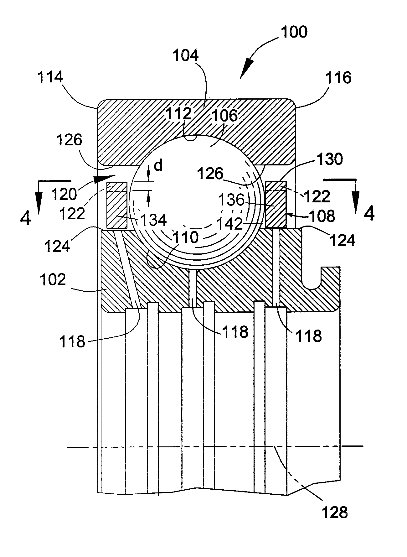
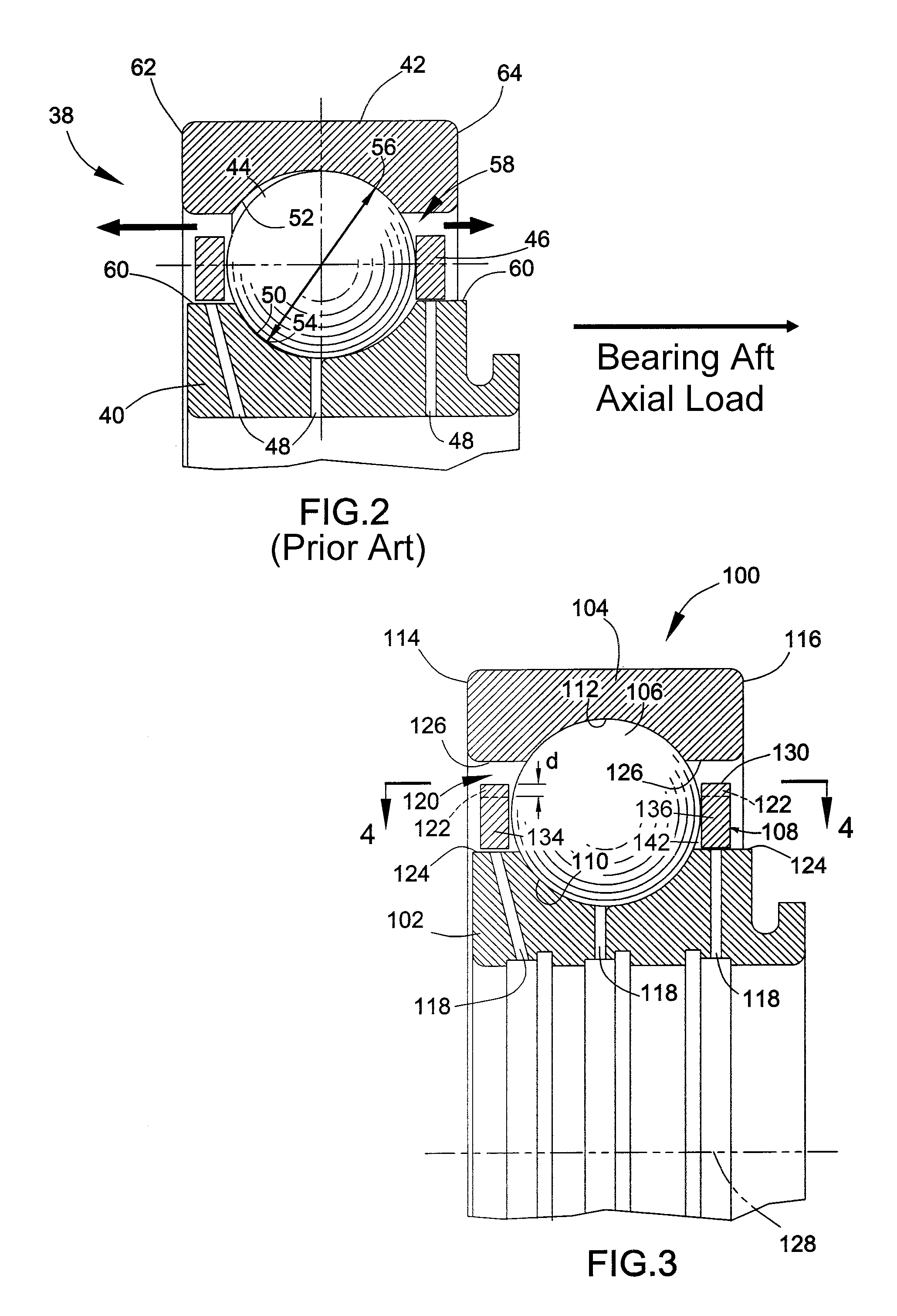
[0024]FIG. 3 schematically represents a rolling element bearing 100 for the purpose of describing aspects of the present invention. It should be noted that the drawings are drawn for purposes of clarity when viewed in combination with the following description, and therefore are not necessarily to scale. To facilitate the description of the bearing 100 provided below, the terms “vertical,”“horizontal,”“lateral,”“front,”“rear,”“side,”“forward,”“rearward,”“upper,”“lower,”“above,”“below,”“right,”“left,” etc., may be used in reference to the perspective of the orientation of the bearing 10 in FIG. 3, and therefore are relative terms and should not be otherwise interpreted as limitations to the construction, installation and use of the bearing 100.

[0025]As represented in FIG. 3, the bearing 100 has a similar construction to that of the bearing represented in FIG. 2. As such, the bearing 100 is represented as a ball bearing that comprises an inner race 102, an outer race 104 that circumsc...


PUM


Abstract

Dynamically-lubricated bearings and methods of dynamically lubricating bearings, including bearings used in gas turbine engines. Such a bearing includes an inner race having an inner race groove, an outer race having an outer race groove that opposes the inner race groove, rolling elements disposed between the inner and outer races and in rolling contact with the inner and outer race grooves, and a cage disposed between the inner and outer races to maintain separation between the rolling elements. A lubricant is introduced into a cavity between the inner and outer races, and rotation of the inner race relative to the outer race causes air to enter pockets of the cage that contain the rolling elements, which in turn causes the lubricant to exit the cavity of the bearing.

Description

BACKGROUND OF THE INVENTION[0001]The present invention generally relates to bearings and more particularly to bearings of the type that are dynamically lubricated, wherein the bearings are configured to inhibit viscous heating of the lubricant and thereby operate at relatively lower temperatures.[0002]FIG. 1 schematically represents a high-bypass turbofan engine 10 of a type known in the art. The engine 10 is schematically represented as including a nacelle 12 and a core engine module 14. A fan assembly 16 located in front of the core module 14 includes an array of fan blades 18. The core module 14 is represented as including a high-pressure compressor 22, a combustor 24, a high-pressure turbine 26 and a low-pressure turbine 28. Air is drawn into the inlet duct 20 of the engine 10 and then compressed by the compressor 22 before being delivered to the combustor 24, where the compressed air is mixed with fuel and ignited to produce hot combustion gases that pass through the turbines 2...

Claims


Application Information

Patent Timeline
IPC IPC(8): F02C7/06F16C33/66F16C33/38F16C33/58
CPCF16C33/6677F16C33/6681F16C2360/23F16C33/3887F16C33/583F16C33/3843F16C33/6662F16C19/06F16C2240/40
Inventor CARTER, BRUCE ALANSANGLI, PRADEEP HEMANTPOTNURU, SANTOSH KUMARCHOURASIA, LAXMIKANT
Owner GENERAL ELECTRIC CO
Why Eureka
Try Eureka