
Variable-Tooth-Thickness Worm-Type Tool and Method For Using The Same To Fabricate Gears

a worm-type tool and variable thickness technology, applied in the direction of gear teeth, gear-teeth manufacturing apparatus, manufacturing tools, etc., can solve the problems of twisted gear flanks, complicated programming and computation, and prior art has to spend more money on modifying tools, so as to reduce the twist of tooth flanks, high-efficiency gear-crowing, and enhance the control of the tool machine

Inactive Publication Date: 2013-04-11
NATIONAL CHUNG CHENG UNIV
View PDF7 Cites 17 Cited by
  • Summary
  • Abstract
  • Description
  • Claims
  • Application Information

AI Technical Summary

Benefits of technology

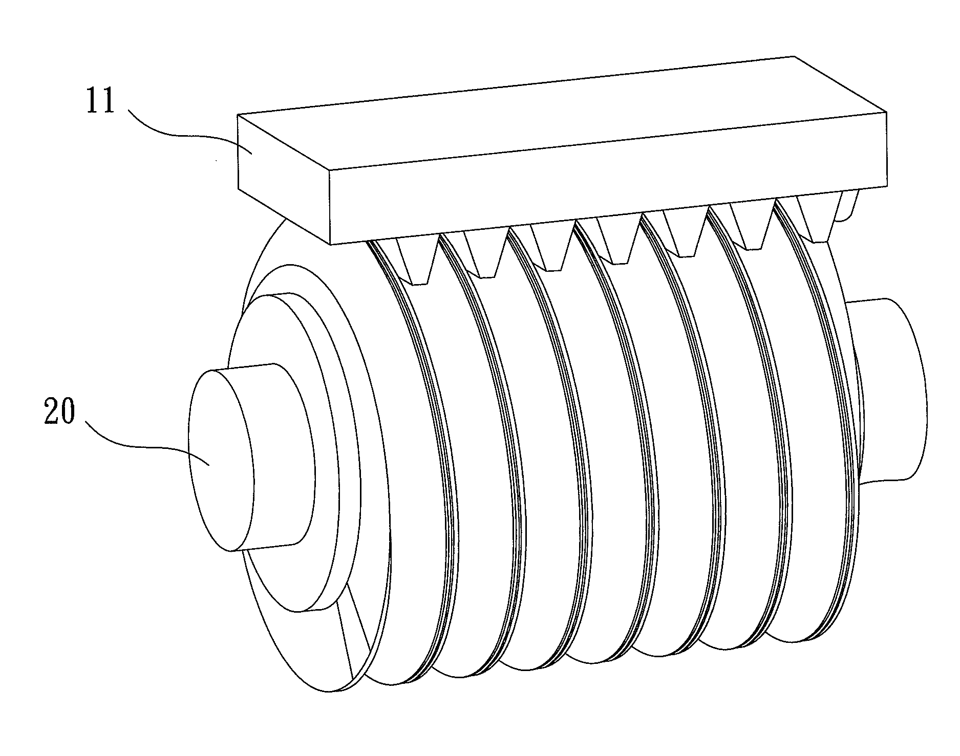
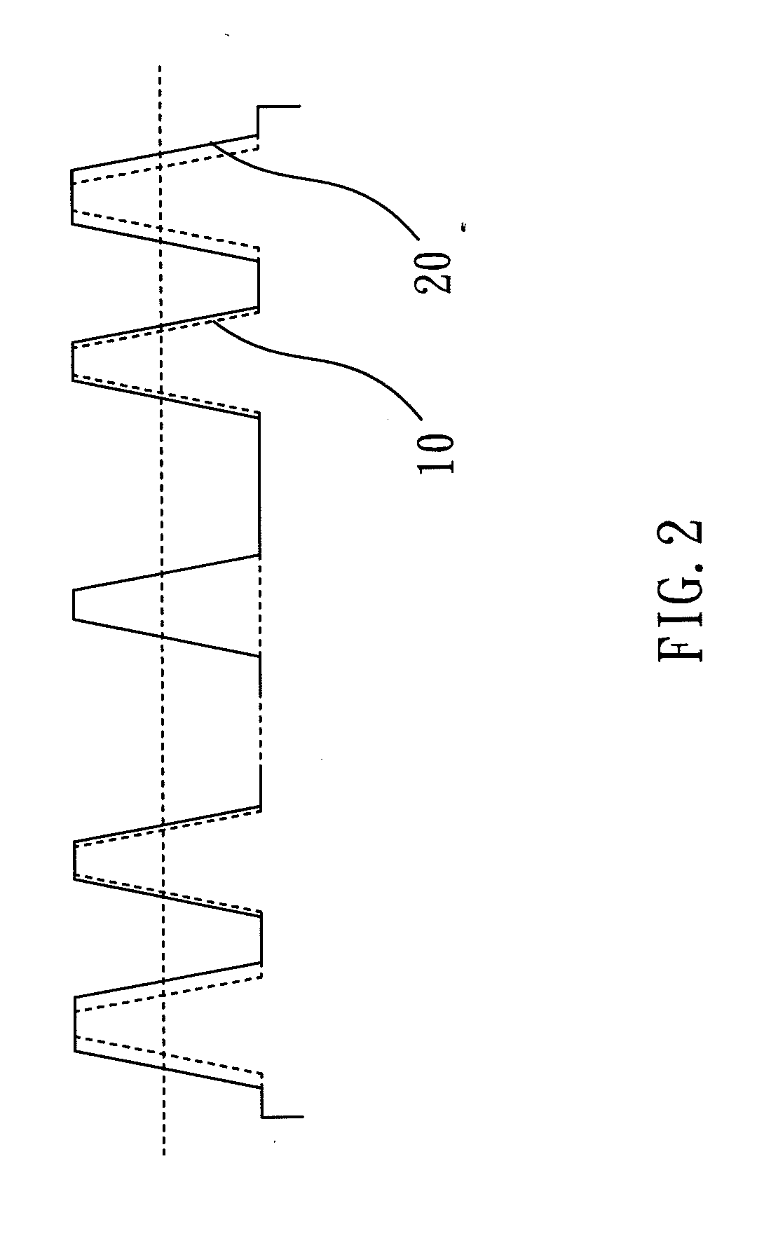
The present invention provides a VTT worm-type tool that can solve the problem of twisted tooth flanks without adding extra degrees of freedom or complexity. The tool cooperates with a generative-type tool machine, and the main body of the tool is installed in the tool holder. The DOF control mechanism can control the tool holder with longitudinal, tangential, and inclined angle degrees of freedom. The VTT worm-type tool has a variable tooth thickness that allows for a constant distance between the centers of the tool and the workpiece. This tool can efficiently and accurately crown gears and prevent twisting of tooth flanks. The method of using the VTT worm-type tool is also provided, which allows for the fabrication of cylindrical gears in high efficiency and low cost. Overall, the present invention provides a cost-effective and efficient tool for gear-crowning.

Problems solved by technology

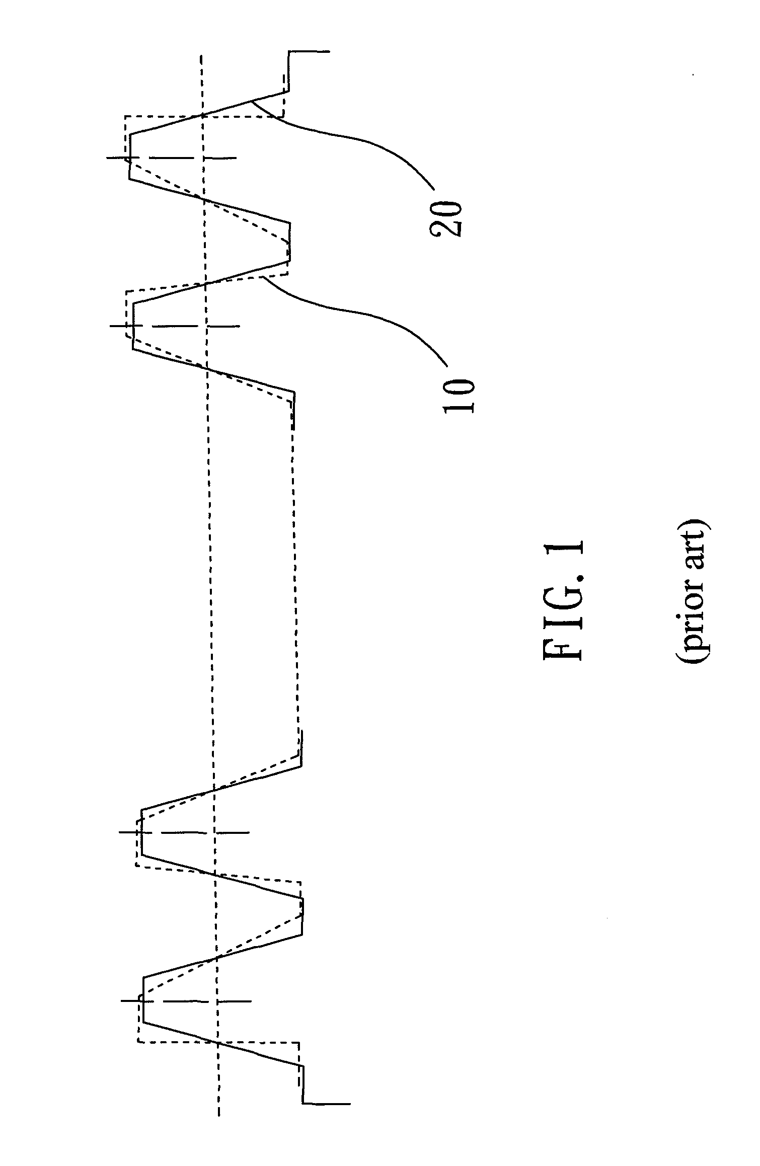
However, such a technology will cause twisted gear flanks unless the crossed angle of the axes of the tool and the worked gear is varied in a very complicated way.
Therefore, the prior art has to spend more money on modifying the tool.
Further, programming and computation for too modification and gear fabrication is pretty complicated in the prior art.
However, the conventional technology only uses a single side of the tool to process the tooth flanks, and the other side of the tool does not undertake tooth flank processing.
Although the conventional technology can prolong the service of the tool, it has lower fabrication efficiency.
Further, it does not solve the problem of twisted gear flanks.
Therefore, the conventional technologies have relatively higher costs.
However, they do not necessarily reduce the twist of tooth flanks.
However, the conventional technologies would cause twisted tooth flanks unless the crossed angle between the axes of the tool and the worked gear.
Consequently, the tooth flanks are usually twisted, and the precision of the assembled machine is likely to be affected by that.

Method used


Image

  • Variable-Tooth-Thickness Worm-Type Tool and Method For Using The Same To Fabricate Gears
  • Variable-Tooth-Thickness Worm-Type Tool and Method For Using The Same To Fabricate Gears
  • Variable-Tooth-Thickness Worm-Type Tool and Method For Using The Same To Fabricate Gears

Examples


Embodiment Construction

[0029]The present invention proposes a variable-tooth-thickness (VTT) worm-type tool, such as a hob, a blade-type tool or a worm-type grinder. The present invention also proposes a method for using a VTT worm-type tool to fabricate a gear. In the present invention, the VTT worm-type tool cooperates with the longitudinal and tangential feeds of a tool machine to lead-crown gears and modify tooth profile, whereby to reduce tooth flank twists. The present invention needn't vary the distance between the centers of the tool and the worked gear but mainly focuses on controlling the longitudinal movement of the tool machine. The present invention not only exempts the user from complicated DOF setting but also exempts the worked gear from tooth flank twist. Therefore, the present invention can crown cylindrical gears in low cost and high efficiency.

[0030]Refer to FIG. 2 showing the structure of a VTT worm-type tool according to one embodiment of the present invention. In the embodiment show...


PUM

PropertyMeasurementUnit
Thicknessaaaaaaaaaa
Distanceaaaaaaaaaa

Abstract

A variable-tooth-thickness worm-type tool comprises a main body and a spiral blade distributed on the main body and featuring variable tooth thickness. The main body and the spiral blade are respectively described with a rack cutter coordinate system and a tool coordinate system. The vector parameters based on the rack cutter coordinate system are transformed into vector parameters based on the tool coordinate system so as to simulate the main body with a rack cutter and develop the spiral blade to have variable tooth thickness. Thus, when a gear blank is tooled, the distance between the centers of the tool holder and the workpiece holder can be set as a constant, and the feed in the radial degree-of-freedom can be neglected, with twists of tooth flanks being inhibited.

Description

BACKGROUND OF THE INVENTION[0001]1. Field of the Invention[0002]The present invention relates to a tool for fabricating gears, particularly to a variable-tooth-thickness worm-type tool for fabricating gears.[0003]2. Description of the Related Art[0004]Refer to FIG. 1 for a conventional worm-type tool, which applies to a generative-type gear fabrication machine to produce various cylindrical gears. Cylindrical gears are indispensable components for automobile industry, machinery industry, electromechanical industry and even aerospace industry. The current industry normally installs a worm-type tool in a generative-type gear fabrication machine to perform precision crowning and tapering processes of cylindrical gears, wherein the lead crowing of cylindrical gears are realized via varying the distance between the centers of the tool and the worked gear. However, such a technology will cause twisted gear flanks unless the crossed angle of the axes of the tool and the worked gear is vari...

Claims


Application Information

Patent Timeline
IPC IPC(8): B23F15/00B23F21/00
CPCB23F21/026B23F21/16Y10T407/17Y10T409/107473B23F13/02Y10T409/104929
Inventor FONG, ZHANG-HUAHSU, RUEI-HUNGWANG, WEI-HSIANG
Owner NATIONAL CHUNG CHENG UNIV
Learn More