
Steering Head with Integrated Drilling Dynamics Control

a drilling dynamics and control technology, applied in the direction of adaptive control, directional drilling, instruments, etc., can solve the problems of reducing the lifetime of the drill string, impairing drilling efficiency, rough cutting of the formation, etc., and achieve the effect of reducing the vibration of the drill string

Active Publication Date: 2013-04-18
BAKER HUGHES INC
View PDF5 Cites 70 Cited by
  • Summary
  • Abstract
  • Description
  • Claims
  • Application Information

AI Technical Summary

Benefits of technology

The patent describes a way to reduce vibrations caused by a drill string in a borehole. This is done by measuring the vibrations and then applying a force against the wall of the borehole to reduce those vibrations. The technical effect is smoother drilling and better stability of the drill string.

Problems solved by technology

Drilling the formation generally causes vibrations on the drill string which can cause wear to the drill string, reduce lifetime of the drill string, impair drilling efficiency and lead to rougher cutting of the formation.

Method used


Image

  • Steering Head with Integrated Drilling Dynamics Control
  • Steering Head with Integrated Drilling Dynamics Control
  • Steering Head with Integrated Drilling Dynamics Control

Examples


Embodiment Construction

[0015]A detailed description of one or more embodiments of the disclosed apparatus and method are presented herein by way of exemplification and not limitation with reference to the Figures.

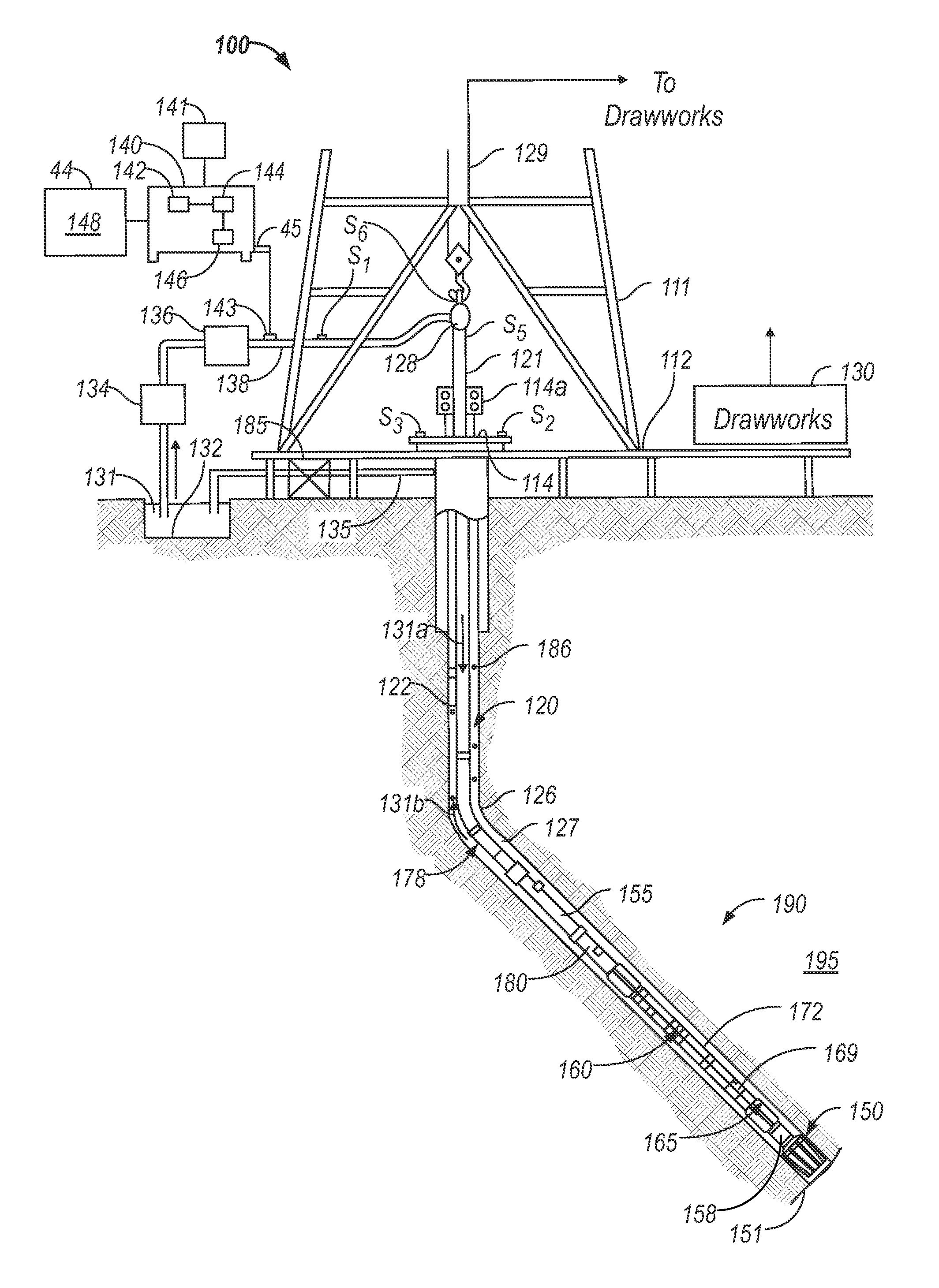
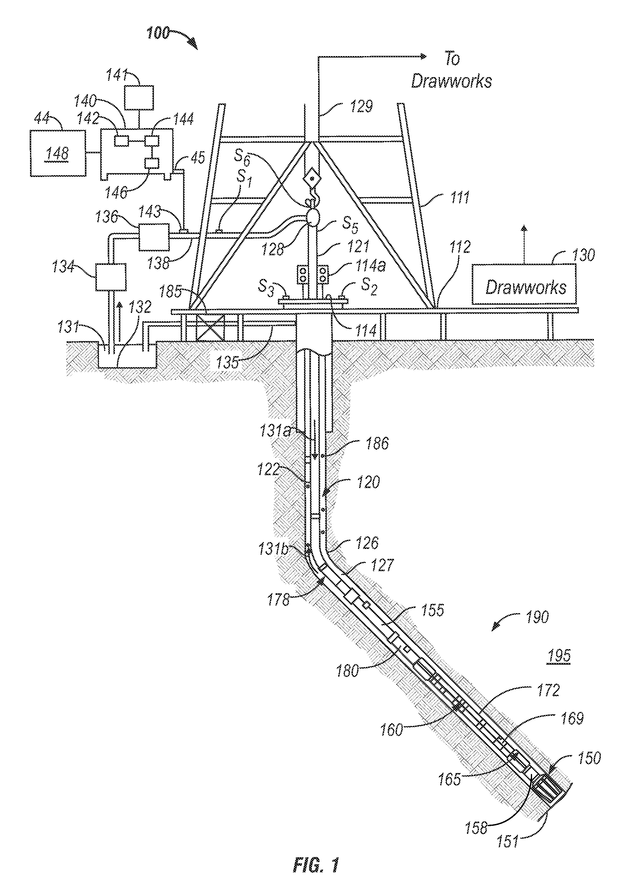
[0016]FIG. 1 is a schematic diagram of an exemplary drilling system 100 that includes a drill string having a drilling assembly attached to its bottom end that can be operated according to the exemplary methods apparatus disclosed herein. FIG. 1 shows a drill string 120 that includes a drilling assembly or bottomhole assembly (“BHA”) 190 conveyed in a wellbore 126. The drilling system 100 includes a conventional derrick 111 erected on a platform or floor 112 which supports a rotary table 114 that is rotated by a prime mover, such as an electric motor (not shown), at a desired rotational speed. A tubing (such as jointed drill pipe) 122 having the drilling assembly 190 attached at its bottom end extends from the surface to the bottom 151 of the wellbore 126. A drill bit 150, attached to drilling as...


PUM


Abstract

A method, apparatus and computer-readable medium for reducing a vibration of a drill string in a borehole. A sensor of the drill string obtains one or more measurements of a parameter of the vibration. A processor determines at least one force for controlling the measured vibration from the measured parameter. At least one actuator applies the determined at least one force against the borehole wall to control the vibration of the drill string.

Description

CROSS REFERENCE TO RELATED APPLICATIONS[0001]This application claim priority to U.S. Provisional Application Ser. No. 61 / 547,433, filed Oct. 14, 2011.BACKGROUND[0002]Drilling operations generally include a drill string conveyed in a borehole to a formation. A drill bit at a bottom end of a drill string is operated to disintegrate the formation. Drilling the formation generally causes vibrations on the drill string which can cause wear to the drill string, reduce lifetime of the drill string, impair drilling efficiency and lead to rougher cutting of the formation. The present disclosure therefore provides a method and apparatus for controlling vibrations on the drill string.BRIEF DESCRIPTION[0003]In one aspect, the present disclosure provides a method of reducing a vibration of a drill string in a borehole, including: obtaining one or more measurements of a parameter of the vibration of the drill string; and applying at least one force against a wall of the borehole responsive to the...

Claims


Application Information

Patent Timeline
IPC IPC(8): E21B7/24G05B13/00
CPCE21B44/00E21B17/07E21B7/062
Inventor HUMMES, OLOFMEISTER, MATTHIASKRUEGER, SVENSANTELMANN, BERNDKOPPE, MICHAEL
Owner BAKER HUGHES INC
Learn More