
Multiple-led emitter for a-19 lamps

a technology of led emitters and lamps, which is applied in the field of multi-led emitters for lamps, can solve the problems of short life, low energy efficiency of incandescent light bulbs, and difficulty in developing led-based lamps for general illumination

Active Publication Date: 2013-04-18
LEDENGIN
View PDF6 Cites 19 Cited by
  • Summary
  • Abstract
  • Description
  • Claims
  • Application Information

AI Technical Summary

Benefits of technology

The present invention relates to high power LED emitter modules that provide wide-angle output light. These modules can be used in various applications such as replacing conventional incandescent A-19 lamps. The LED A-19 lamp has a single emitter with multiple LEDs and a single lens that can provide wide-angle light output. The emitter has a plurality of LEDs disposed over a single recess in a substrate and a single lens disposed over the LEDs and substrate. The LED A-19 lamp has a wide-angle light distribution and can be used in various applications such as replacing conventional A-19 lamps. The substrate includes a plurality of base layers, electrical contacts, and electrical paths. The emitter also has a plurality of light-emitting diodes disposed over the substrate. The LED A-19 lamp has a unique design that allows for high power and wide-angle light output without the need for additional secondary optical components.

Problems solved by technology

The incandescent light bulbs suffer from low energy efficiency and short lifetime as they produce more heat than light.
However, the development of LED-based lamps for general illumination has run into various difficulties.
Among these is the difficulty of mass-producing lamps that provide high power light at a wide-angle.
For example, conventional LED-based lamps for replacing the A-19 incandescent bulbs are limited in their brightness, often produce light at 40 W incandescent equivalent with a power consumption of, e.g., 7-9 Watts.
In part due to the size limitation of the A-19 bulbs, it is difficult to provide high power wide-angle LED emitters that are suitable for A-19 bulb applications.

Method used


Image

  • Multiple-led emitter for a-19 lamps
  • Multiple-led emitter for a-19 lamps
  • Multiple-led emitter for a-19 lamps

Examples


Embodiment Construction

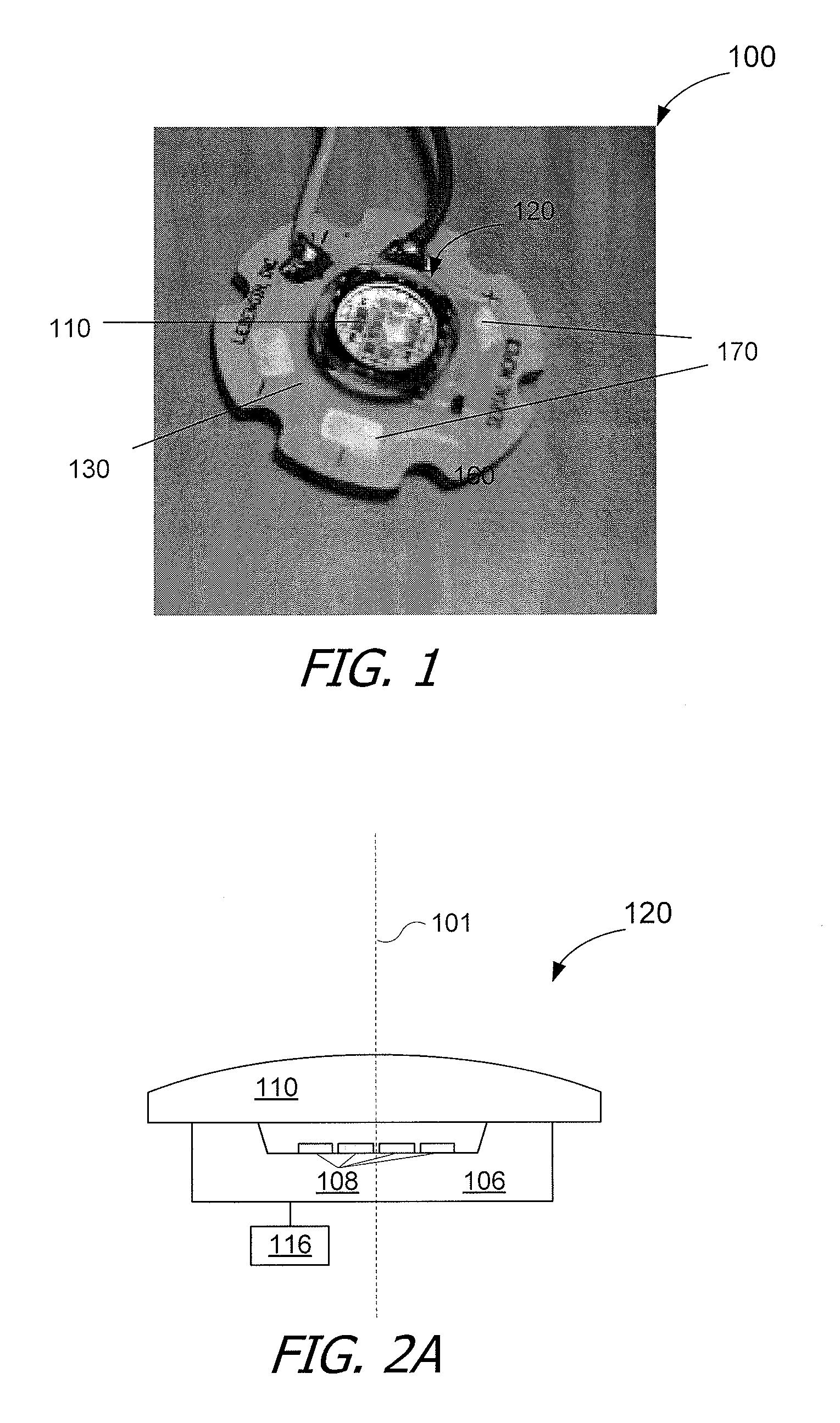
[0027]The description below is presented with reference to a series of drawing figures enumerated above. These diagrams are merely examples, and should not unduly limit the scope of the claims herein. In connection with the various aspects illustrated and described, one of ordinary skill in the art would recognize other variations, modifications, and alternatives.

[0028]FIG. 1 is a simplified cross-sectional view illustrating an A-19 light bulb having a high-power light-emitting diode (LED) emitter according to an embodiment of the present invention. As shown in FIG. 1, emitter module 100 includes a multiple-LED emitter 120 overlying a circuit board 130. Emitter 120 has two or more groups of light-emitter diodes (LEDs), with each group including one or more LEDs. Emitter 120 also has a single lens 110 disposed over the LEDs. As described below with reference to FIGS. 2A-3D, the groups of LEDs are individually addressable. In other words, each group can receive a different amount of e...


PUM

PropertyMeasurementUnit
electrical poweraaaaaaaaaa
sizeaaaaaaaaaa
diameteraaaaaaaaaa

Abstract

An LED (light-emitting diode) high-power wide-angle A-19 lamp needs only a single LED emitter having multiple LEDs. The LED A-19 lamp includes a lamp envelop structure configured for transmission of light therethrough and a base structure coupled to a lower portion of the lamp envelop structure for coupling to an external power source. The dimensions of the lamp envelop structure and the base structure conform to requirement of a conventional A-19 lamp. The LED emitter includes a plurality of light-emitting diodes (LEDs) disposed in a single recess in a substrate and a single lens disposed over the LEDs and the substrate. In a specific embodiment, the emitter is configured to consume electrical power of 30 Watts or higher and to provide light distribution at 130 degrees or wider at 50% peak intensity without additional secondary optical components.

Description

CROSS-REFERENCES TO RELATED APPLICATIONS[0001]This application is related to U.S. patent application Ser. No. 12 / 756,861, filed Apr. 8, 2010, entitled “Package for Multiple Light Emitting Diodes,” which has been published as U.S. Patent App. Pub. No. 2010 / 0259930 (Attorney Docket No. 91924-793987—000510US), and U.S. patent application Ser. No. 13 / 106,808, filed May 12, 2011, entitled “Tuning Of Emitter With Multiple LEDS To A Single Color Bin” (Attorney Docket No.: 91924-793987—001200US). The disclosures of both are incorporated by reference in their entirety herein.BACKGROUND OF THE INVENTION[0002]The present invention relates in general to lighting devices based on light-emitting diodes (LEDs) and in particular to LED emitters for lamps that can replace conventional A-19 incandescent lamps.[0003]Among traditional incandescent light bulbs, the A-19 lamp, having a mushroom-shaped glass bulb, is the most popular. The widest part of the light bulb generally has a diameter of 19 / 8 inch...

Claims


Application Information

Patent Timeline
Patent Type & Authority Applications(United States)
IPC IPC(8): H05B37/02F21V5/04
CPCF21V5/04F21Y2113/005F21V3/00F21K9/135F21K9/50F21V13/02H01L2924/0002F21Y2101/02H01L25/0753H01L2924/00F21K9/232F21K9/60F21Y2115/10F21Y2113/13F21V13/08
Inventor JIANG, WU
Owner LEDENGIN
Learn More