Surveillance system and method

a surveillance system and surveillance method technology, applied in the field of surveillance systems and surveillance methods, can solve problems such as restrictions on and achieve the effect of increasing the detection range of objects and increasing the accuracy of object detection

Active Publication Date: 2013-04-18
HANWHA VISION CO LTD
View PDF33 Cites 16 Cited by
  • Summary
  • Abstract
  • Description
  • Claims
  • Application Information

AI Technical Summary

Benefits of technology

[0008]One or more exemplary embodiments provide a radar transmitter, a radar receiver, a surveillance system including the radar transmitter and the radar receiver, and a surveillance method that use the surveillance system capable of increasing an object detection range.
[0029]According to the exemplary embodiments, an object detection range may be increased by the surveillance system separately including the radar transmitter and the radar receiver. Moreover, the accuracy of object detection may be increased by periodical synchronization.

Problems solved by technology

General civilian radar sensors restricted by local regulations have restrictions on an object detection range due to a limitation in an intensity of RF radiation power.

Method used


Image

  • Surveillance system and method
  • Surveillance system and method
  • Surveillance system and method

Examples


Embodiment Construction

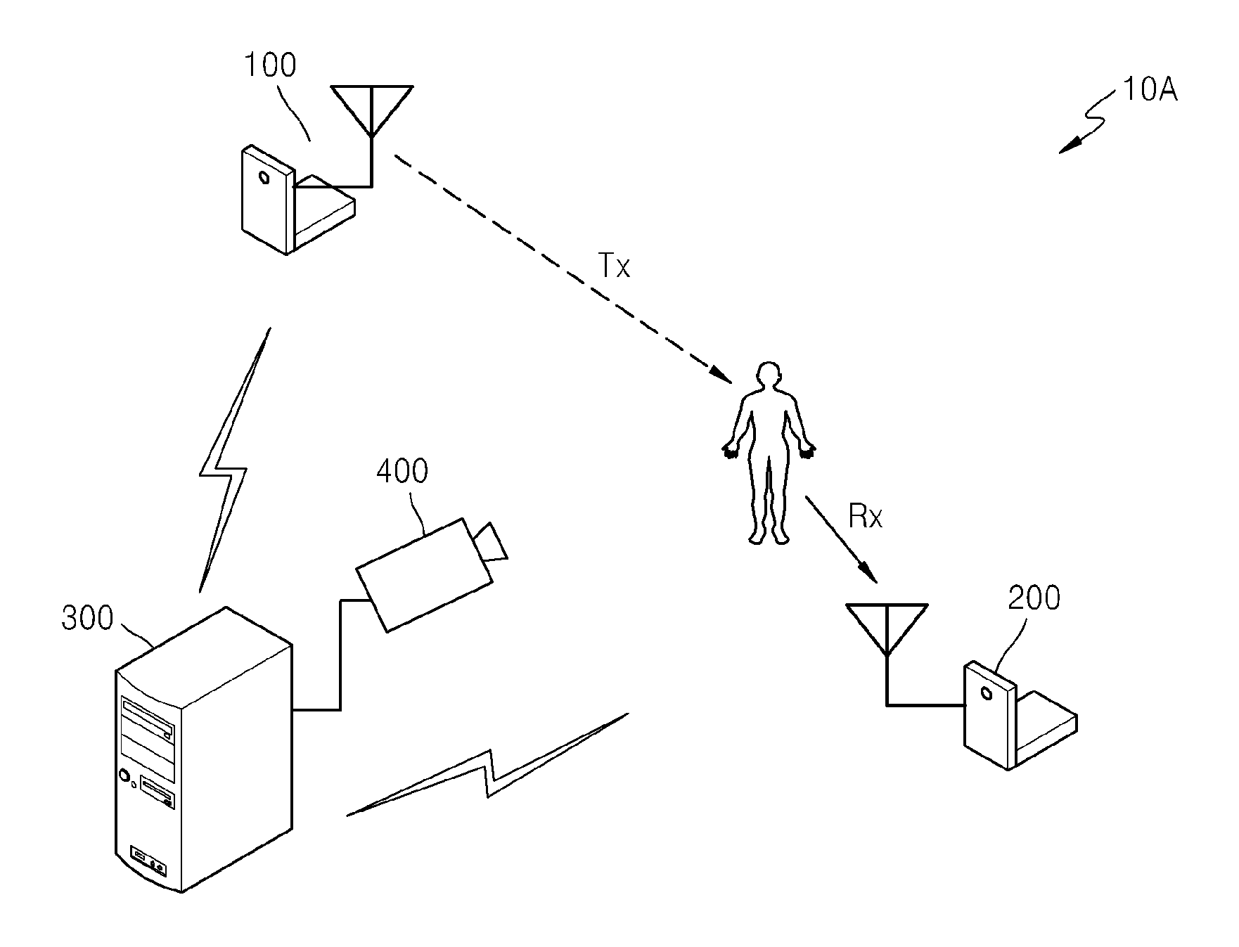
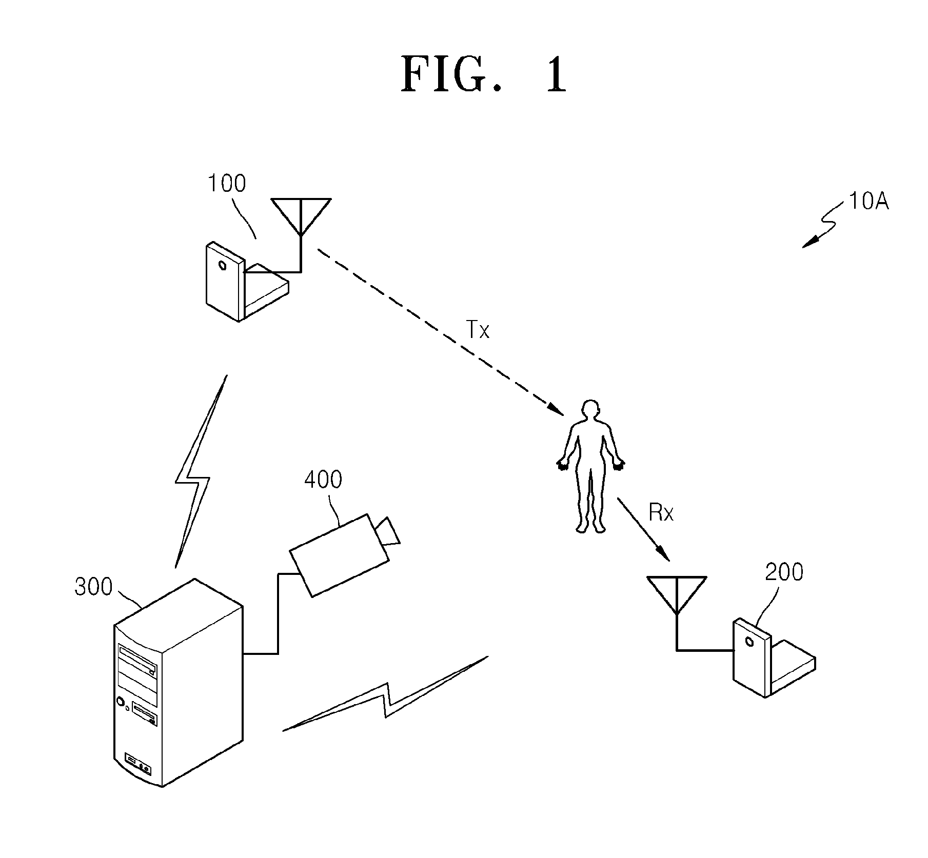
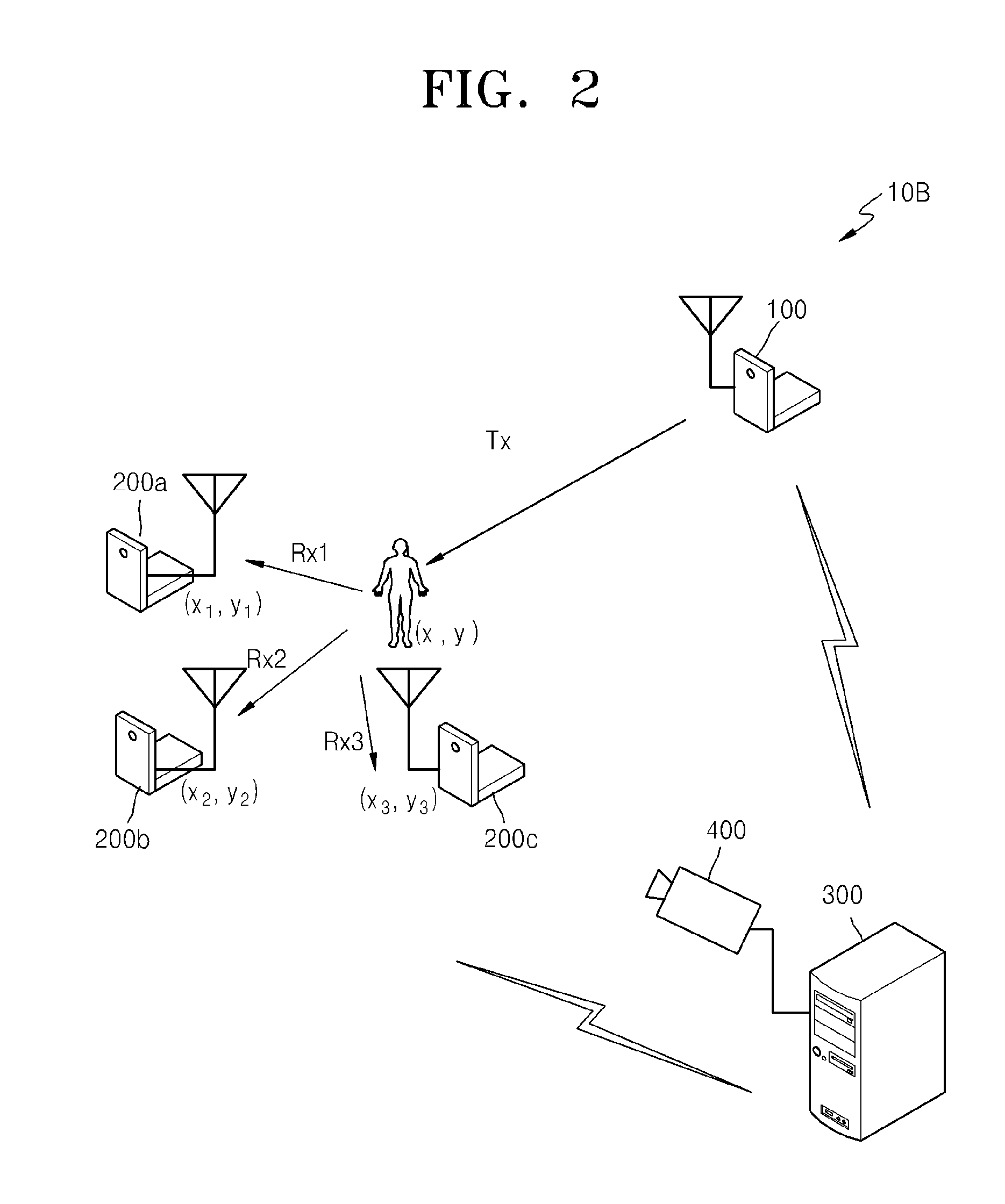
[0040]Hereinafter, exemplary embodiments will be described more fully with reference to the accompanying drawings. Like numbers refer to like elements throughout. In the description of the exemplary embodiments, if it is determined that a detailed description of commonly-used technologies or structures related to the inventive concept may unnecessarily obscure the subject matter of the exemplary embodiments, the detailed description will be omitted.

[0041]It will be understood that, although the terms ‘first’, ‘second’, ‘third’, etc., may be used herein to describe various elements, these elements should not be limited by these terms. These terms are only used to distinguish one element from another element. For example, a first element discussed below could be termed a second element, and similarly, a second element may be termed a first element without departing from the teachings of this disclosure. Moreover, a series of processes according to the exemplary embodiments include not...


PUM


Abstract

Provided is a surveillance system including a radar transmitter which transmits a detection signal to an object existing within a surveillance region, and at least one radar receiver which is installed separate from the radar transmitter within the surveillance region, receives a signal reflected by the object, and predicts a signal distance of the object which is a sum of a distance from the radar transmitter to the object and a distance from the object to the at least one radar receiver.

Description

CROSS-REFERENCE TO RELATED PATENT APPLICATION[0001]This application claims priority from Korean Patent Application No. 10-2011-0105536, filed on Oct. 14, 2011, in the Korean Intellectual Property Office, the disclosure of which is incorporated herein in its entirety by reference.BACKGROUND[0002]1. Field[0003]Apparatuses and method consistent with exemplary embodiments relate to a surveillance system and a surveillance method that use a radar sensor.[0004]2. Description of the Related Art[0005]Radar sensors detect and track an object that enters a surveillance region, and ascertain information about a location of the object, by using a radio frequency (RF) signal as a radar signal.[0006]FIG. 11 is a schematic view of a related art radar sensor 1 including a transceiver 12. Referring to FIG. 11, the related art radar sensor 1 includes an antenna 11, the transceiver 12, and a signal processing unit 13. The transceiver 12 outputs a radar signal to an object via the antenna 11 and receiv...

Claims


Application Information

Patent Timeline
Patent Type & Authority Applications(United States)
IPC IPC(8): G01S13/08
CPCG08B13/19695G01S13/867G01S13/003G01S7/4004
Inventor JEON, KI-YONG
Owner HANWHA VISION CO LTD
Why Eureka
Try Eureka