Autofocus based on differential measurements

a technology of differential measurement and autofocus, applied in the field of digital pathology, can solve the problems of limiting the system throughput, not being able to determine the sign of focus error, and disadvantageous for a continuous autofocus system that needs permanent updates, so as to improve the autofocus function of scanning microscop

Active Publication Date: 2013-04-18
KONINKLIJKE PHILIPS ELECTRONICS NV
View PDF3 Cites 16 Cited by
  • Summary
  • Abstract
  • Description
  • Claims
  • Application Information

AI Technical Summary

Benefits of technology

[0017]Since the S-curve comprises less high frequency detail than the first and second autofocus image data, determination of the zero crossing of the S-curve may be performed with high accuracy thus enabling to determine the polar error signal with high accuracy.

Problems solved by technology

However, this procedure may be both prone to errors and be also time-consuming, thereby limiting the throughput of the system.
In known autofocus imaging systems it may not be possible to determine the sign of the focus error (above or below focus), i.e. the focus error signal may not be polar.
This may be disadvantageous for a continuous autofocus system that needs permanent updates on the optimum focus setting.

Method used


Image

  • Autofocus based on differential measurements
  • Autofocus based on differential measurements
  • Autofocus based on differential measurements

Examples


Embodiment Construction

[0036]The illustration in the drawings is schematically. In different drawings, similar or identical elements are provided with the same reference numerals. In the following, the character prime (′) associated to a symbol will mean that the image space is considered (e.g.

[0037]sensor reference) while a symbol without prime character will mean that the object space is considered (typically the sample reference). For example, when the angle Beta prime (β′) will be used in this description, a rotation in image space, and, as will be described more specifically, a rotation of the physical sensor, will be indicated. Also, an angle Beta (β without prima) will indicate a rotation in object space, and as will be described more specifically a rotation of an oblique cross section of the sample that is imaged by the autofocus sensor.

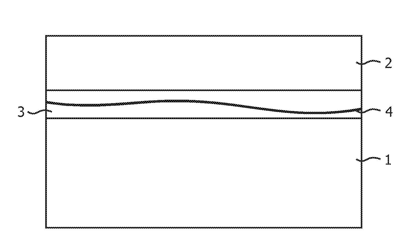
[0038]FIG. 1 shows a schematic cross-section of a tissue slide assembly, comprising a microscope slide 1, having a typical thickness of 1 mm, a cover slip 2, with ...


PUM


Abstract

The present invention relates to the field of digital pathology and in particular to whole slide scanners. A tilted autofocus image sensor images an oblique cross-section of the slide. For focusing multiple sequential overlapping images, which have been taken by the tilted sensor, are compared. The axial position of the tissue layer can be determined from the polar error signal resulting from this differential measurement.

Description

FIELD OF THE INVENTION[0001]The present invention relates to the field of digital pathology and other fields of rapid microscanning In particular, the present invention relates to an autofocus imaging system for a microscope, a microscope comprising an autofocus imaging system, a method for autofocus imaging of a microscope, a computer-readable medium and a program element.BACKGROUND OF THE INVENTION[0002]In digital pathology and particular in the case of whole slide scanning, specimens are sliced and imaged for analysis purposes as well as teaching purposes. Line sensors may be used for scanning a whole tissue slide. These slide scanners may perform a continuous mechanical scanning, thereby reducing stitching problems and allowing for the use of so-called time delay integration (TDI) line sensors in order to accommodate for low brightness of the illumination, as for example disclosed in WO 01 / 84209 A2.[0003]Before the actual scanning the optimum focus position may be determined at ...

Claims


Application Information

Patent Timeline
Patent Type & Authority Applications(United States)
IPC IPC(8): H04N5/232
CPCG02B21/241H04N5/23212G02B21/367G02B21/244G02B21/245H04N23/673H04N23/90G02B21/002G02B21/365
Inventor HULSKEN, BAS
Owner KONINKLIJKE PHILIPS ELECTRONICS NV
Why Eureka
Try Eureka