
Multi-Level DC/AC Converter

a converter and multi-level technology, applied in the field of dc/ac converters, can solve the problems of low direct voltage generated by photovoltaic panels or other alternative sources, heavy output filters, and low efficiency, and achieve the effects of reducing harmonic content, reducing output voltage, and increasing the number of voltage levels

Active Publication Date: 2013-04-18
ABB (SCHWEIZ) AG
View PDF9 Cites 45 Cited by
  • Summary
  • Abstract
  • Description
  • Claims
  • Application Information

AI Technical Summary

Benefits of technology

The invention provides a converter capable of generating multiple voltage levels, resulting in a reduction of harmonic content in the output voltage. This also offers advantages in terms of reducing losses and component costs.

Problems solved by technology

In general, the direct voltage generated by a photovoltaic panel, or another alternative source, is relatively low and not constant, because of the change in parameters, such as irradiation conditions, which may oscillate slowly and regularly because of the apparent movement of the sun, or rapidly and unpredictably because of transiting clouds and / or of the change in other climate parameters, such as humidity.
These circuits have a first drawback due to the complexity and to the cost deriving from the step-up stage.
Moreover, the wave form of the voltage output from the converter has a high harmonic content and hence requires a very heavy output filter, with consequent additional costs.
The electronic switches of the bridge (designed as MOSFET, IGBT or other suitable components) are subject to a high voltage difference when the chopping module or the DC / DC converter is active and they switch at high voltage, with consequent high losses and need to be dimensioned for high voltage ratings.
The arrangement is such that the switches controlled by the two branches of the half-bridge and the two switches of the two branches positioned in parallel to the branches of the half-bridge must be designed for high voltage values, in such a way as to support the voltage of the highest level, with consequent costs and low efficiency because of the high switching losses.

Method used


Image

  • Multi-Level DC/AC Converter
  • Multi-Level DC/AC Converter
  • Multi-Level DC/AC Converter

Examples


Embodiment Construction

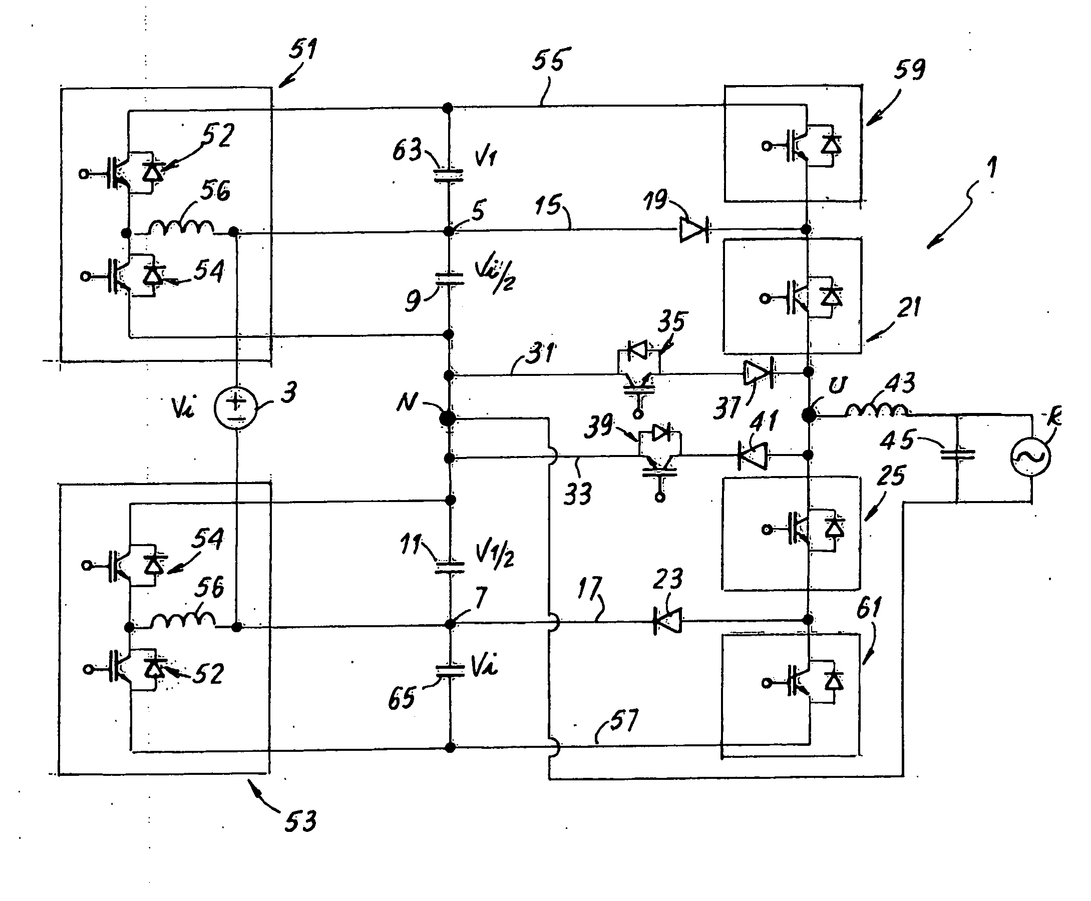
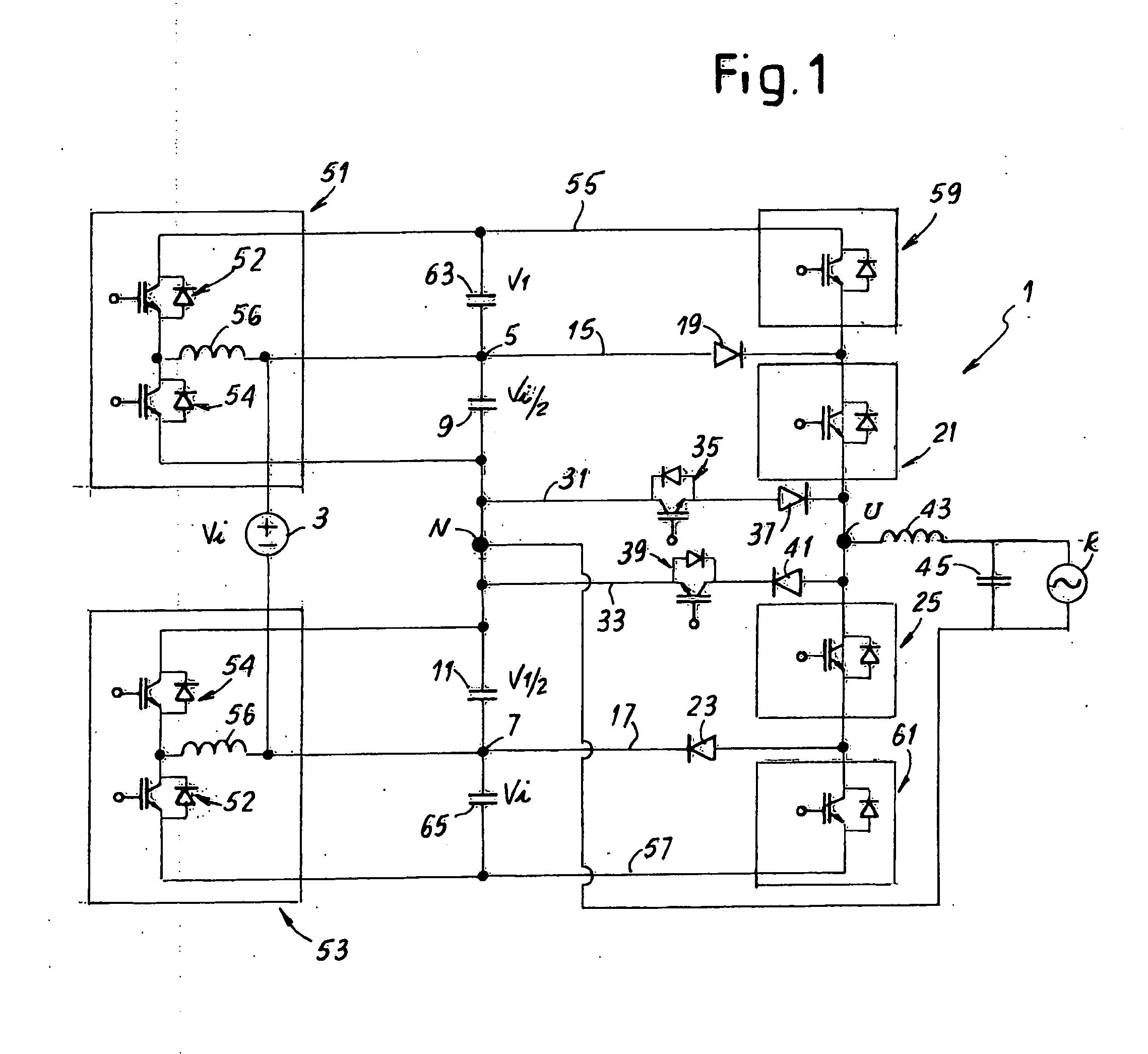
[0040]FIG. 1 shows a first circuit diagram of a converter according to the invention, indicated as a whole with reference number 1. Reference number 3 indicates a direct voltage source, e.g. a group of photovoltaic panels, which supplies an input voltage Vi. The source 3 is connected to two input connections 5 and 7 of the converter 1. More in particular, in the diagram of FIG. 1 the positive pole of the source 3 is connected to the connection 5 and the negative pole of the source 3 is connected to the connection 7.

[0041]Reference numbers 9 and 11 indicate two capacitors connected respectively between the connection 5 and the neutral N and between the connection 7 and the neutral N of the converter 1. The voltage Vi of the source 3 is split at the ends of the two capacitors 9 and 11, across the plates of each capacitor being present a voltage difference of Vi / 2. Therefore, the input voltage of the converter 1, referred to the neutral N, is Vi / 2.

[0042]To the connections 5 and 7 a hal...


PUM


Abstract

The multi-level DC / AC converter, comprising: an input (5,7) connectable to a direct voltage source (3), with a first connection (5) and a second connection (7) between which can be applied an input voltage (Vi); a half-bridge with a first controlled switch (21) and a second controlled switch (25) between which is positioned an output (U) of the converter; a first connecting branch (15) between the first controlled switch (21) and the first connection (5) and a second connecting branch (17) between the second controlled switch (25) and the second connection (7); a third controlled switch (59) associated to the first controlled switch (21), connectable in series to the first controlled switch to generate an output voltage exceeding a first limit value (Vi / 2); a fourth controlled switch (61) associated to the second controlled switch (25), connectable in series to said second controlled switch to generate an output voltage below a second limit value (−Vi / 2).

Description

TECHNICAL FIELD[0001]The present invention relates to improvements to DC / AC converters and more specifically to multi-level PWM converters.STATE OF THE ART[0002]In many industrial applications, it is required to convert a direct current into alternating current at a predetermined voltage. For this purpose, DC / AC converters or inverters are used. Typical examples of uses of these circuits are found in the field of renewable energies or of alternative energies. Photovoltaic panels, for example, represent sources of direct electrical energy, which is used to supply power to local loads in alternating current, or which is injected into the normal AC electrical energy distribution grid. Other applications in the field of alternative energies contemplate the use of different types of direct current sources, e.g. wind generators, fuel cells, etc.[0003]In general, the direct voltage generated by a photovoltaic panel, or another alternative source, is relatively low and not constant, because...

Claims


Application Information

Patent Timeline
Patent Type & Authority Applications(United States)
IPC IPC(8): H02M7/483
CPCH02M7/49H02M7/483H02M3/158H02M7/487H02M1/007H02M7/4833
Inventor MARTINI, DAVIDVALIANI, MASSIMOSOLDANI, SIMONE
Owner ABB (SCHWEIZ) AG
Learn More