
X-ray ct apparatus and control method thereof

Active Publication Date: 2013-04-18
HITACHI LTD
View PDF11 Cites 11 Cited by
  • Summary
  • Abstract
  • Description
  • Claims
  • Application Information

AI Technical Summary

Benefits of technology

The present invention provides an X-ray CT apparatus that can generate high-quality X-ray CT images for each region and part of an object in cone-beam CT imaging using a plane detector. This helps to suppress an increase in computation time. For example, in chest to abdomen imaging, the apparatus can generate an image with high resolution in the small absorption region of the chest and a low-contrast image with excellent resolution in the large absorption region of the abdomen.

Problems solved by technology

Generally, as the body thickness of a scanned part increases, the output value of an X-ray detector decreases and its error increases.
For this reason, noise of an X-ray CT image reconstructed for a region with a large body thickness increases.
For this reason, there have been cases in which an optimal X-ray CT image can be provided for a certain part of the object but the optimal image quality is not obtained for other regions.

Method used


Image

  • X-ray ct apparatus and control method thereof
  • X-ray ct apparatus and control method thereof
  • X-ray ct apparatus and control method thereof

Examples


Embodiment Construction

[0032]Hereinafter, embodiments of an X-ray CT apparatus related to the present invention will be described in detail using the accompanying drawings. In all drawings for explaining the embodiments of the present invention, the same reference numerals are given to elements with the same functions, and repeated explanation thereof will be omitted.

[0033]

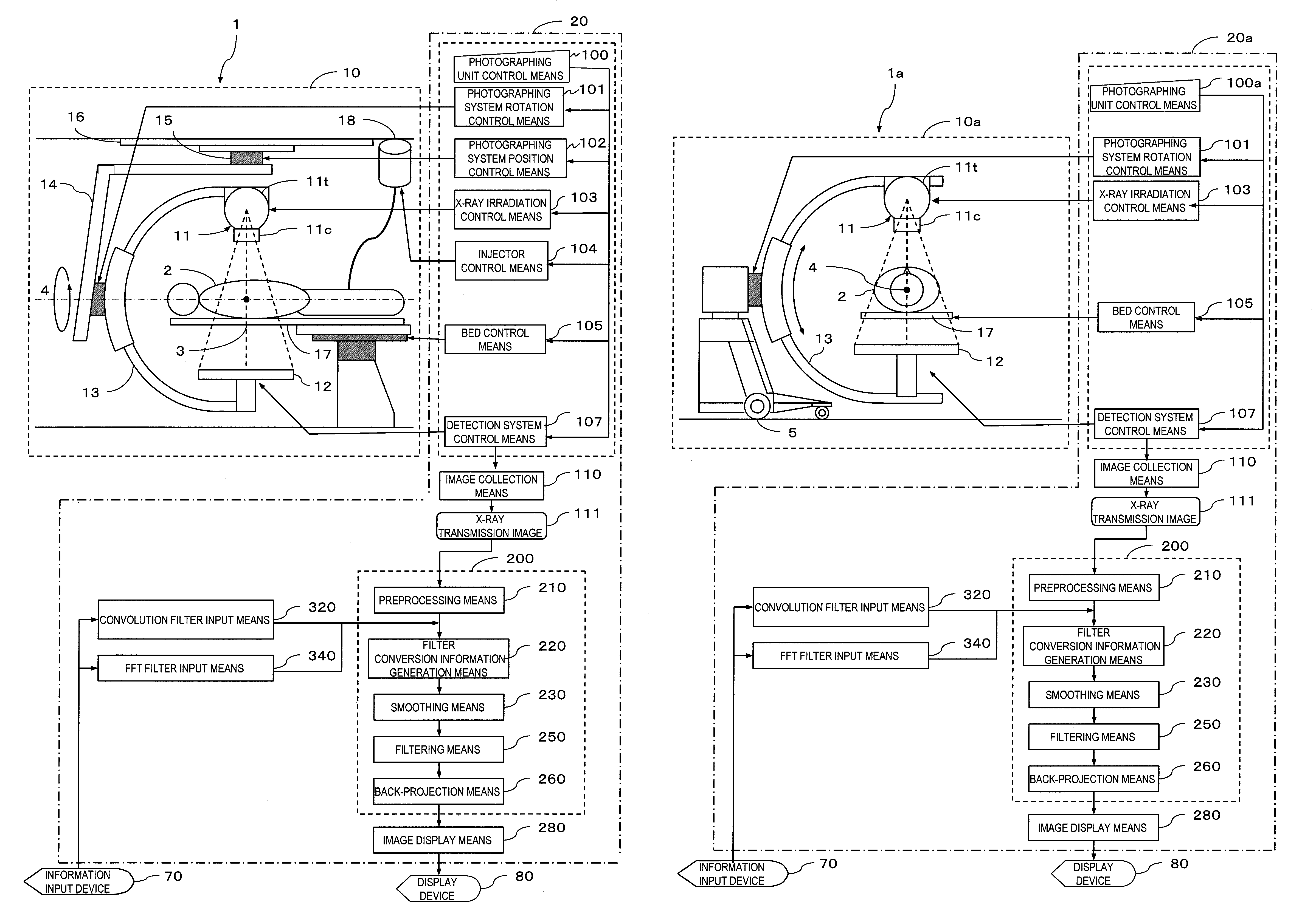
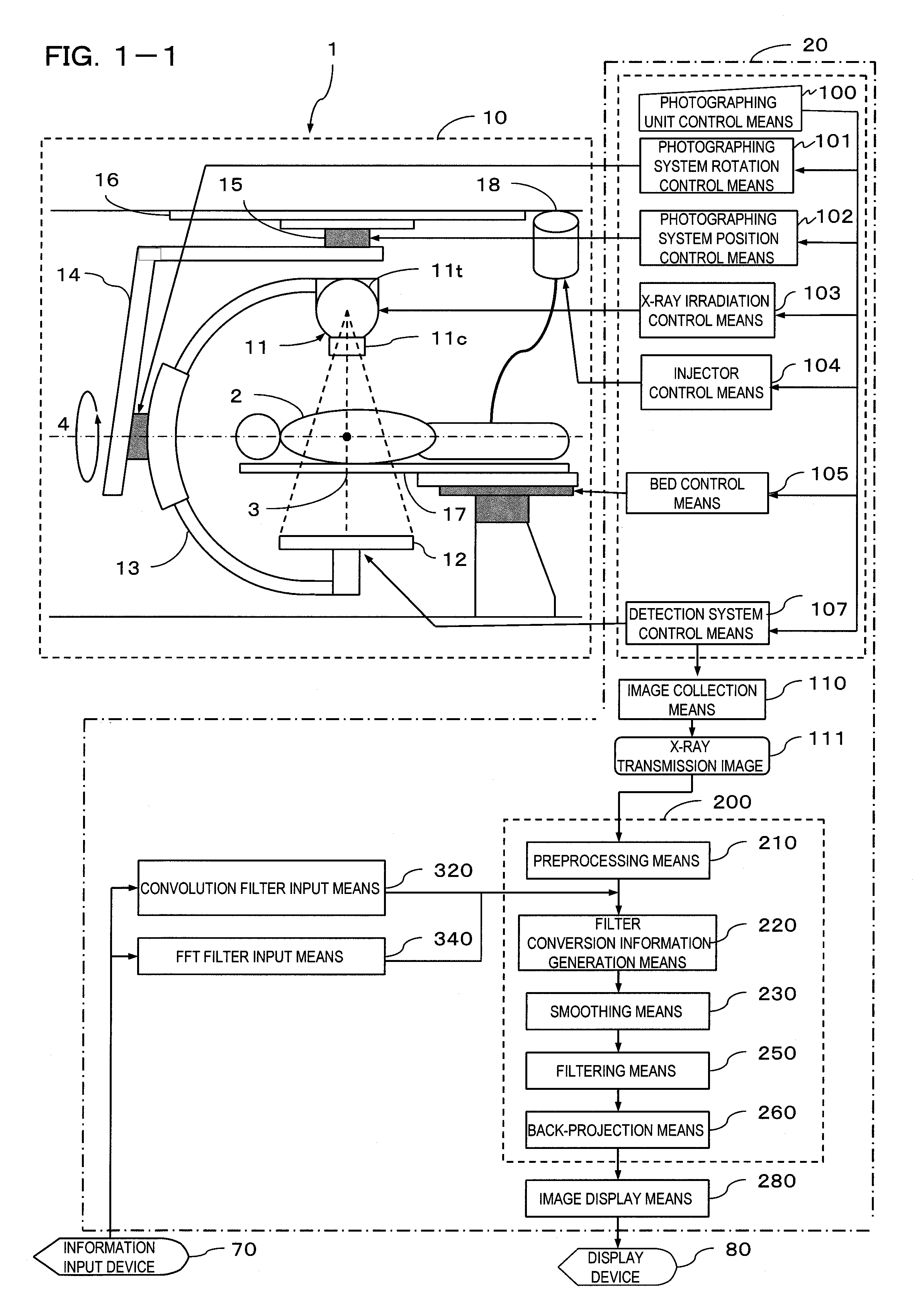
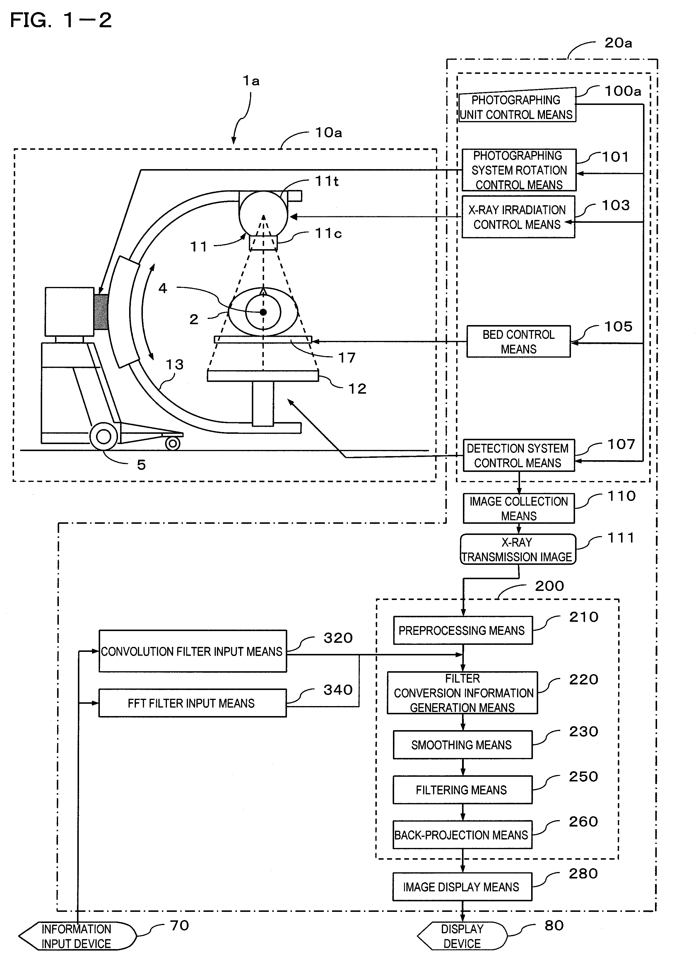
[0034]First, the schematic configuration of a cone-beam X-ray CT apparatus to which the present invention is applied will be described on the basis of FIGS. 1-1 and 1-2. FIG. 1-1 is a schematic configuration diagram showing a cone-beam X-ray CT apparatus (C-arm type) 1 to which the present invention is applied. FIG. 1-2 is a schematic configuration diagram showing a C-arm type cone-beam X-ray CT apparatus 1a mounted in a movable X-ray apparatus to which the present invention is applied.

[0035]The cone-beam X-ray CT apparatus 1 shown in FIG. 1-1 includes an imaging unit 10 that irradiates an object 2 with X-rays and captures an X-ray tran...


PUM


Abstract

In order to generate an X-ray CT image with optimal quality for each part and each region of an object when scanning the object across a plurality of parts using a plane detector, there is provided an X-ray CT apparatus including smoothing means 230 and filtering means 250 for generating a convolution filter on the basis of feature amounts of projection data output from the X-ray detector 12 and superimposing the convolution filter on the projection data, reconstruction means 200 for generating an X-ray CT image of the object by performing a reconstruction operation on the projection data on which the convolution filter is superimposed, and image display means 280 for displaying the image generated by the reconstruction means 200.

Description

TECHNICAL FIELD[0001]The present invention relates to an X-ray CT apparatus and in particular, to an X-ray CT apparatus that generates an X-ray CT image with optimal quality for each part and each region of an object when scanning the object across a plurality of parts using a plane detector, and a control method thereof.BACKGROUND ART[0002]Generally, as the body thickness of a scanned part increases, the output value of an X-ray detector decreases and its error increases. For this reason, noise of an X-ray CT image reconstructed for a region with a large body thickness increases. On the other hand, in a conventional X-ray CT apparatus, an X-ray CT image of an object has usually been generated using one reconstruction filter in each CT scan. For this reason, there have been cases in which an optimal X-ray CT image can be provided for a certain part of the object but the optimal image quality is not obtained for other regions.[0003]In such a case, there is known an X-ray CT apparatus...

Claims


Application Information

Patent Timeline
IPC IPC(8): G01N23/04
CPCA61B6/032A61B6/5205A61B6/5258G06T2211/421G01N23/046G06T11/006Y10S378/901
Inventor OKABE, MASAKAZU
Owner HITACHI LTD
Learn More