Memory-based device and method of channel estimation in a digital communication receiver

a digital communication and channel estimation technology, applied in the field of telecommunication systems, can solve the problems of high complexity and power consumption, and achieve the effect of increasing computation time and remarkably reducing the complexity of the hardware of the rake receiver

Inactive Publication Date: 2009-08-18
TELECOM ITALIA SPA +1
View PDF18 Cites 0 Cited by
  • Summary
  • Abstract
  • Description
  • Claims
  • Application Information

AI Technical Summary

Benefits of technology

[0055]The Applicant has verified that the hardware complexity of a Rake receiver can be remarkably reduced, in relation to prior art architectures, and that a slightly increase in computation time is offset by the greatly reduced complexity.

Problems solved by technology

The matched filter (DDA) and the bank of correlators (CDA) offer faster path detection than other solutions but they present high complexity and power consumption.

Method used


Image

  • Memory-based device and method of channel estimation in a digital communication receiver
  • Memory-based device and method of channel estimation in a digital communication receiver
  • Memory-based device and method of channel estimation in a digital communication receiver

Examples


Embodiment Construction

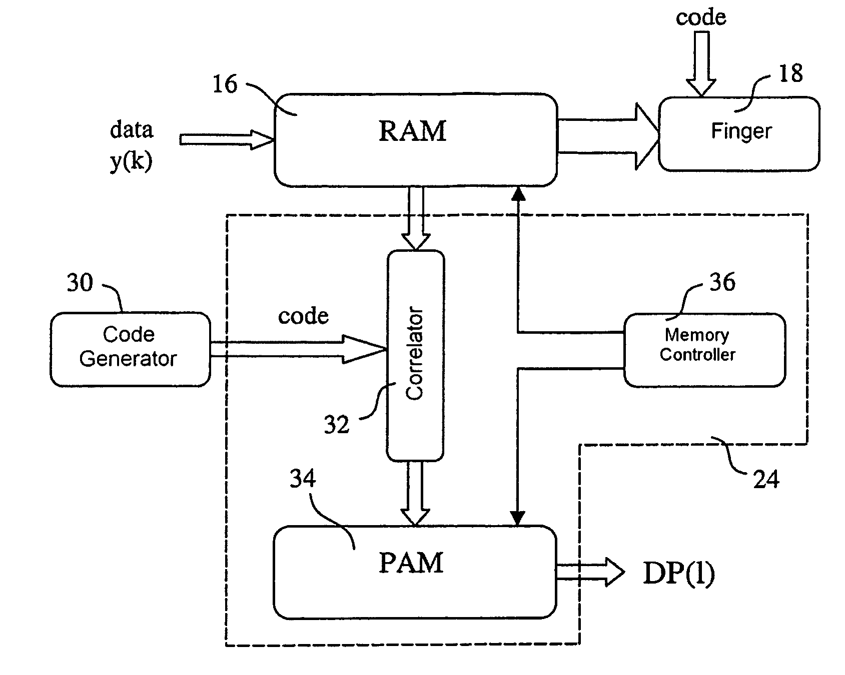
[0066]The FIG. 6 shows a block diagram of a digital communication receiver, realized according to a first aspect of the present invention (DDA architecture). A Rake receiver 10 receives an input signal y(k), sampled at N times the chip frequency FC, from a receiver front end, not shown in figure. The input signal y(k) feeds a Random Access Memory 16, with size equal to the channel delay spread of H+T+1 chips, and a delay profile estimation unit 24.

[0067]The delay profile estimation unit 24 computes the time delays and amplitudes of each received multipath component and it provides, as output, a channel profile energy DP(1), where 1 is the variable spanning the channel delay spread.

[0068]From a functional point of view the Rake receiver 10 is a modular device made by a plurality of independent receiving units, named fingers 18, each tuned to a different replica of the transmitted signal. Each finger F1 . . . Fn performs the operations of descrambling, despreading and integration on t...


PUM


Abstract

A spread spectrum digital communication receiver, of the type comprising an input memory buffer (16) for storing samples of an input signal (y(k)) and a code generator circuit (30) for generating a re-generated user code, incorporates a device (24) for the estimation of a channel delay profile comprises: a basic correlator (32) having a first input (41) for sequentially reading from a memory location of the input memory buffer (16) a plurality of samples of the input signal (y(k)), a second input (43) for receiving from the code generator circuit (30) a re-generated user code, and an output terminal for generating, by means of a correlation operation between the plurality of samples of the input signal and the regenerated user code, a first value of the channel delay profile energy (DP(1)); and a memory controller circuit (36) for addressing said the memory buffer (16) so that the first input (41) of the basic correlator (32) is successively fed with the content of several memory locations of the memory buffer (16), each addressing operation corresponding to a new correlation operation of the basic correlator (32) for the computation of a new value of the channel delay profile energy (DP(1)).

Description

CROSS REFERENCE TO RELATED APPLICATIONS[0001]This application is the US national phase of PCT application PCT / EP2002 / 012815 filed 15 Nov. 2002 with a claim to the priority of PCT patent application PCT / EP2002 / 012815 itself filed 15 Nov. 2002.FIELD OF THE INVENTION[0002]The present invention refers to telecommunication systems and in particular to a digital receiver for use in a CDMA (Code Division Multiple Access) system. The invention also relates to a device and a method for the estimation of the channel delay profile in a digital communication receiver.[0003]The CDMA access technique currently finds widespread use in third generation mobile communication systems (e.g. UMTS, CDMA2000) thanks to its higher spectrum efficiency with respect to other access techniques.[0004]In a CDMA system the data sequence is spread by a pseudo noise code (hereinafter “PN code”) having a broader spectrum width. The efficiency of these systems is highly dependent on the capability of the receiver to ...

Claims


Application Information

Patent Timeline
Patent Type & Authority Patents(United States)
IPC IPC(8): H04B1/00H04B1/707
CPCH04B1/7093H04B1/7113H04B2201/70707H04B1/7117
Inventor ETTORRE, DONATOGRAZIANO, MAURIZIOMELIS, BRUNOFINOTELLO, ANDREAOSSOLI, ALESSANDRORUSCITTO, ALFREDO
Owner TELECOM ITALIA SPA
Why Eureka
Try Eureka