Ablative catheter with electrode cooling and related methods of use

Inactive Publication Date: 2013-04-18
BOSTON SCI SCIMED INC
View PDF11 Cites 175 Cited by
  • Summary
  • Abstract
  • Description
  • Claims
  • Application Information

AI Technical Summary

Benefits of technology

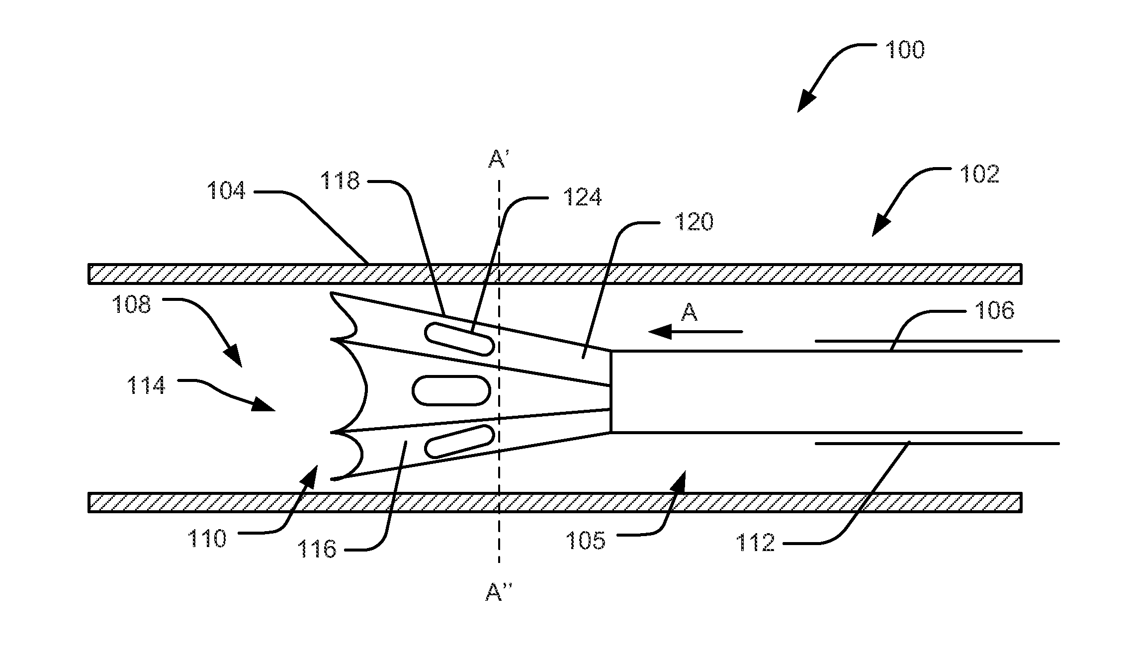
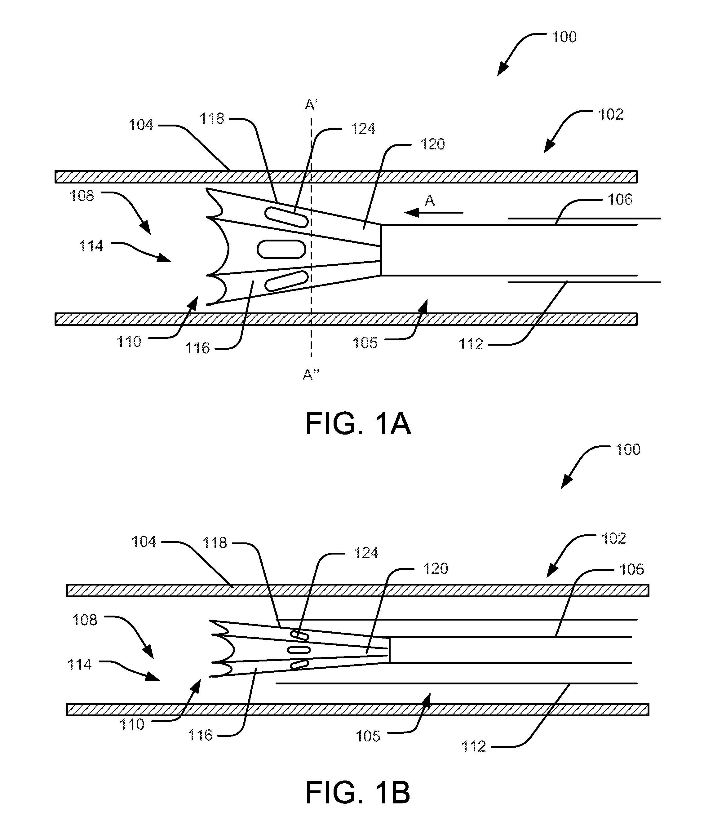
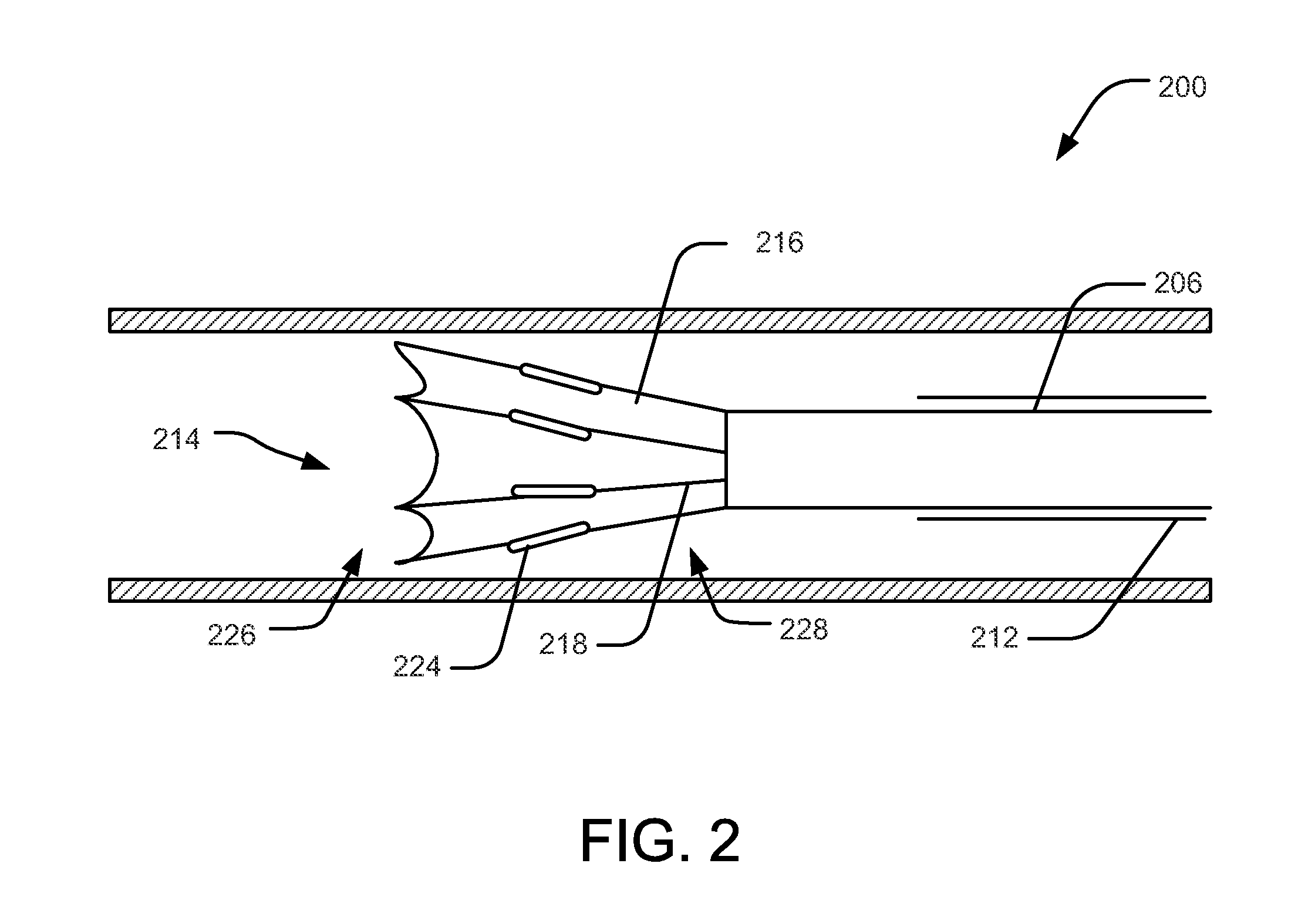
[0012]An example medical device for modulating nerve activity may include a sheath. An elongate shaft may be disposed in the sheath. The shaft may have a distal end. An expandable frame may be attached to the shaft. The frame may include a plurality of struts and a membrane attached to the struts. The frame may be configured to shift between an expanded configuration and a collapsed configuration. The membrane may be configured to partially occlude blood flow through a blood vessel when the frame is in the expanded configuration. One or more electrodes coupled to the frame.
[0013]Another example medical device for modulation of renal nerve activity may include a sheath. An elongate shaft may be slidably disposed within the sheath. The shaft may have a distal region. A self-expanding umbrella frame may be attached to the shaft. The frame may include a plurality of struts and a membrane attached to the struts. The frame may be configured to shift between a collapsed configuration when the frame is disposed within the sheath and a conical configuration when the sheath is disposed proximally of the frame. One or more electrodes may be coupled to the frame. The membrane may define a plurality of pleated regions that extend radially inward relative to the struts when the frame is in the conical configuration. The pleated regions may be configured to increase blood flow adjacent to the electrodes.
[0014]Method for modulating renal nerves are also disclosed. An example method may inc

Problems solved by technology

This treatment, however, may result in thermal injury to the artery walls.
The treatment can also produce undesirable side effects, such as blood damage and clotting, and the high

Method used


Image

  • Ablative catheter with electrode cooling and related methods of use
  • Ablative catheter with electrode cooling and related methods of use
  • Ablative catheter with electrode cooling and related methods of use

Examples


Embodiment Construction

[0021]For the following defined terms, these definitions shall be applied, unless a different definition is given in the claims or elsewhere in this specification.

[0022]All numeric values are herein assumed to be modified by the term “about,” whether or not explicitly indicated. The term “about” generally refers to a range of numbers that one of skill in the art would consider equivalent to the recited value (i.e., having the same function or result). In many instances, the terms “about” may include numbers that are rounded to the nearest significant figure.

[0023]The recitation of numerical ranges by endpoints includes all numbers within that range (e.g. 1 to 5 includes 1, 1.5, 2, 2.75, 3, 3.80, 4, and 5).

[0024]As used in this specification and the appended claims, the singular forms “a”, “an”, and “the” include plural referents unless the content clearly dictates otherwise. As used in this specification and the appended claims, the term “or” is generally employed in its sense inclu...


PUM


Abstract

Medical devices and methods for making and using medical devices are disclosed. An example medical device may include an ablative catheter system including an elongate member having a proximal end, a distal end, and a lumen extending there between. An end-effector may be disposed at the distal end of the elongate member. The end-effector may include an expandable frame. A membrane may be supported on the frame. The membrane may be configured to partially occlude fluid flow upon frame expansion. One or more electrodes may be placed on the end-effector. The system may also include a control member that is configured to shift the end-effector between a collapsed state and the frame expansion state.

Description

CROSS-REFERENCE TO RELATED APPLICATIONS[0001]This application claims priority under 35 U.S.C. §119 to U.S. Provisional Application Ser. No. 61 / 548,608, filed Oct. 18, 2011, the entirety of which is incorporated herein by reference.FIELD OF THE INVENTION[0002]Embodiments of the present disclosure relate generally to medical devices suitable for use in body tissue modulation and ablation. In particular, embodiments of the instant disclosure relate to structures and methods for cooling medical devices employed in tissue modulation and ablation.BACKGROUND OF THE INVENTION[0003]Radio frequency ablation (RFA) is a relatively new medical procedure in which tissue is ablated using the heat generated from the radio frequency waves. Unlike the conventional procedures, the RF current does not interfere with the nervous or cardiac system and can be used as a minimally invasive procedure without a general anesthetic. Further, RFA procedures generally require image guidance, such as X-ray screeni...

Claims


Application Information

Patent Timeline
IPC IPC(8): A61B18/14A61B18/18
CPCA61B18/1492A61B2018/00065A61B2018/0016A61B2018/0022A61B2018/00267A61B2018/1861A61B2018/00434A61B2018/00511A61B18/24A61B2018/00577A61B2018/1467A61B2018/00404
Inventor HILL, DAVID M.
Owner BOSTON SCI SCIMED INC
Why Eureka
Try Eureka