
Coolng structure for recovery-type air-cooled gas turbine combustor

Active Publication Date: 2013-04-25
TOHOKU ELECTRIC POWER +1
View PDF5 Cites 40 Cited by
  • Summary
  • Abstract
  • Description
  • Claims
  • Application Information

AI Technical Summary

Benefits of technology

The present invention is about a cooling structure for the recovery-type air-cooled gas turbine combustor, which can effectively cool the walls using the compressor's air. This reduces the amount of air that needs to be pressurized, making it more efficient. The cooling structure utilizes bled and pressurized air to cool the combustor's walls, which are at high and low temperatures, respectively. The reused air is then effectively reused as combustion air, resulting in a gas turbine with improved cooling efficiency.

Problems solved by technology

Recovery-type steam cooling, therefore, is not applicable to a gas turbine alone.

Method used


Image

  • Coolng structure for recovery-type air-cooled gas turbine combustor
  • Coolng structure for recovery-type air-cooled gas turbine combustor
  • Coolng structure for recovery-type air-cooled gas turbine combustor

Examples


Embodiment Construction

[0075]An embodiment of a cooling structure for a recovery-type air-cooled gas turbine combustor according to the present invention will hereinafter be described with reference to the drawings.

[0076]FIG. 4 is a schematic configuration diagram illustrating a gas turbine according to this embodiment, and FIG. 5 is a sectional view illustrating an example of the surrounding structure of a combustor of the gas turbine. The illustrated gas turbine drives a generator, although it is not limited thereto.

[0077]As shown, a gas turbine GT1 is composed of a compressor1, a combustor 30, and a turbine 7 to which a generator Ge is coupled.

[0078]The compressor 1 compresses air taken in from the atmosphere. The main flow of the compressed air is supplied to the combustor 30 through a compressed-air supply passage 2.

[0079]The combustor 30 burns fuel with the compressed air compressed by the compressor 1 to produce a high-temperature, high-pressure combustion gas. The combustion gas is supplied to the...


PUM


Abstract

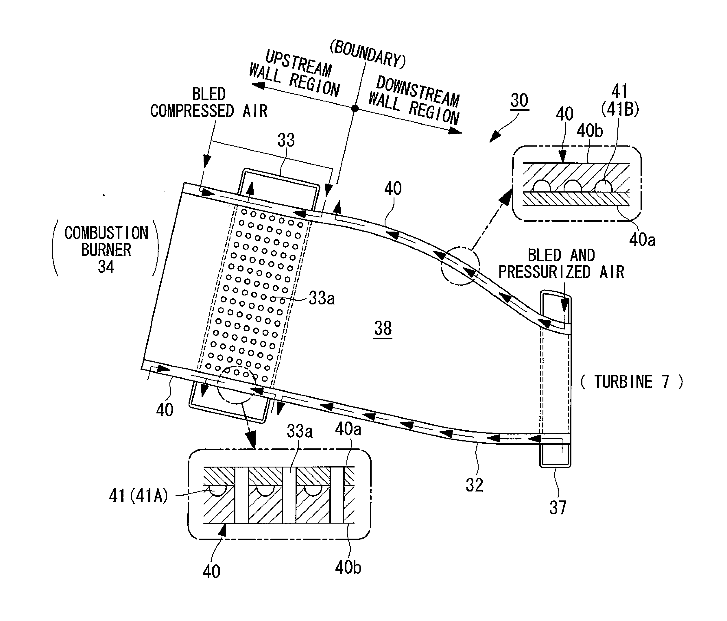
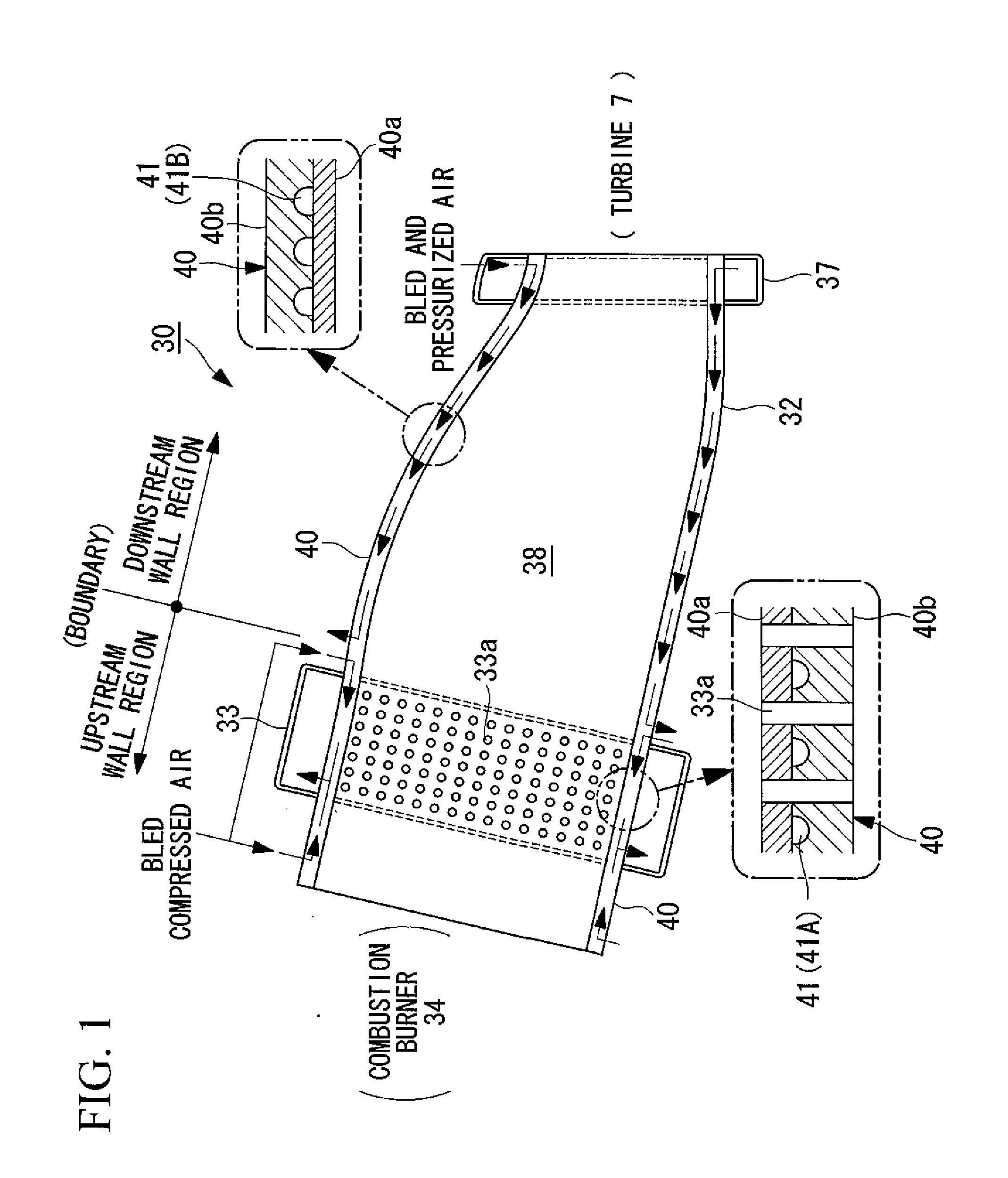
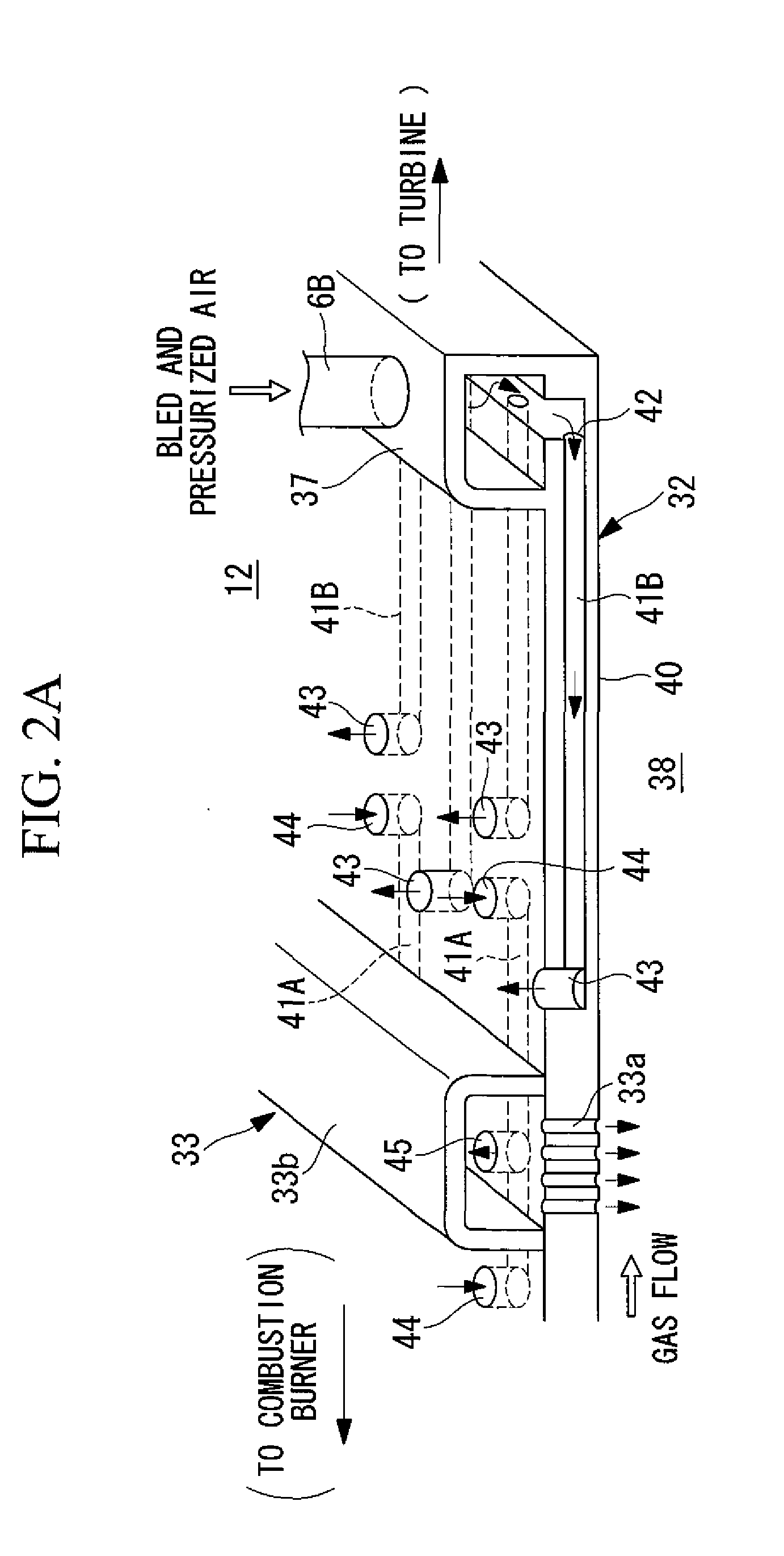
In a cooling structure for a recovery-type air-cooled gas turbine combustor having a recovery-type air-cooling structure that bleeds, upstream of the combustor, and pressurizes compressed air supplied from a compressor, that uses the bled and pressurized air to cool a wall, and that recovers and reuses the bled and pressurized air as combustion air for burning fuel in the combustor together with a main flow of the compressed air, wall cooling in which cooling air is supplied to cooling air passages formed in the wall of the combustor to perform cooling involves a downstream wall region, closer to a turbine, that is cooled using the bled and pressurized air as the cooling air and an upstream wall region, closer to a burner, that is cooled using, as the cooling air, bled compressed air bled from a main flow of the compressed air through a housing inner space.

Description

TECHNICAL FIELD[0001]The present invention relates to cooling structures for recovery-type air-cooled gas turbine combustors.BACKGROUND ART[0002]A gas turbine is an apparatus composed mainly of a compressor, a combustor, and a turbine, and the compressor takes in and compresses air to discharge high-pressure compressed air. The compressed air discharged from the compressor is taken into the combustor and is used as combustion air for burning a gas turbine fuel supplied to the combustor to produce a high-temperature combustion gas. This combustion gas is taken into the turbine and flows between rotor blades and stator blades to drive the turbine, thereby producing output power.[0003]In gas turbines in the related art, internal cooling passages of hot components, such as the combustor, the turbine stator blades, and the turbine rotor blades, are broadly divided into three types: open-type air cooling, recovery-type steam cooling, and recovery-type air cooling.[0004]In open-type air co...

Claims


Application Information

Patent Timeline
IPC IPC(8): F02C7/18F23R3/06F02C7/08
CPCF01D9/023F02C7/08F02C7/18F02C7/24F23R3/06F23R3/005F23R3/44F23R2900/00014F05D2260/202F01D25/00
Inventor MIZUKAMI, SATOSHIISHIGURO, TATSUOMASADA, JUNICHIROTAKATA, KAZUMASATORII, SHUNSUKEFUKUNAGA, YUYAKONISHI, TETSUNISHIMURA, YOSHIAKIIGARASHI, YOSHIAKIISHIKAWA, SHINYA
Owner TOHOKU ELECTRIC POWER
Learn More