Heat Exchanger with heat exchange chambers and plate members utilizing respective medium directing members and method of making same

a technology of heat exchange chamber and plate member, which is applied in the direction of metal-working apparatus, stationary conduit assembly, tubular elements, etc., can solve the problems of reduced pressure resistance, limited efficiency of pipe heat exchanger, and increased damage of thinner tubes, so as to maximize the heat exchange capacity of a heat exchanger and increase the overall surface area of the heat exchanger. , the effect of increasing the surface area

Inactive Publication Date: 2013-04-25
MIKUTAY CORP
View PDF5 Cites 14 Cited by
  • Summary
  • Abstract
  • Description
  • Claims
  • Application Information

AI Technical Summary

Benefits of technology

[0013]In another embodiment of the present invention, more than one chamber may be used, which will further increase the surface area of the enhanced tube for the heat exchanger. Also, a first chamber may be connected directly to another chamber. Furthermore, more than one chamber may be coupled to a plate member. In another embodiment of the present invention, more than one plate member may be coupled to a chamber. When plurality of chambers are coupled to the plate member, the plate member provides an economical means to maximize the heat exchanging capability of a heat exchanger by filling the voids between plurality of column of chambers to increase the overall surface area of the heat exchanger, without greatly increasing the size of a heat exchanger.
[0014]In yet another embodiment of the present invention, the tube size may vary between the chambers, and if more than one chamber is used, the chamber size may vary from one chamber to the next.
[0015]In another embodiment of the present invention, plurality of tube size and chamber size positioned on a plate member may vary from one to the ne

Problems solved by technology

The efficiency of the pipe heat exchangers is limited by the amount of surface area available for the transfer of heat.
However, the pressure resistance is reduced, and the thinner tubes are more prone to damage.
Also, the assembly process is complicated because of the fragile nature of the parts.
In addition, the extruded tubes are prone to plugging during the manufacturing process, particularly if a brazing process is utilized.
The complexity of the extruding process potentially results in higher costs and higher defect rates.
The overall cost for the flat tube heat exchanging system will be higher because a higher powered compressor may be necessary to move the heat exchanging medium through the smaller openings of the tubes.
Conversely, if a higher powered compressor is

Method used


Image

  • Heat Exchanger with heat exchange chambers and plate members utilizing respective medium directing members and method of making same
  • Heat Exchanger with heat exchange chambers and plate members utilizing respective medium directing members and method of making same
  • Heat Exchanger with heat exchange chambers and plate members utilizing respective medium directing members and method of making same

Examples


Embodiment Construction

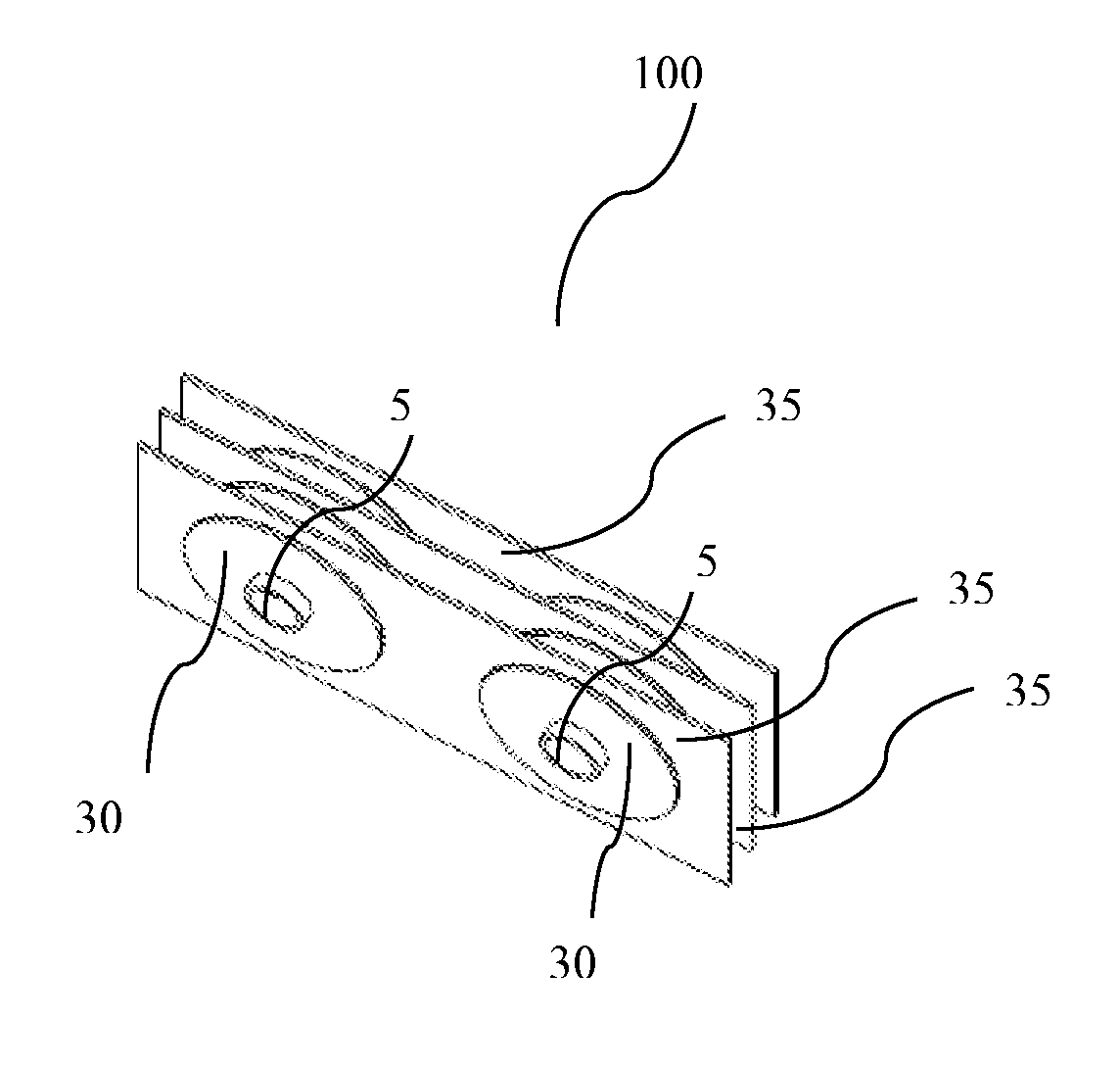
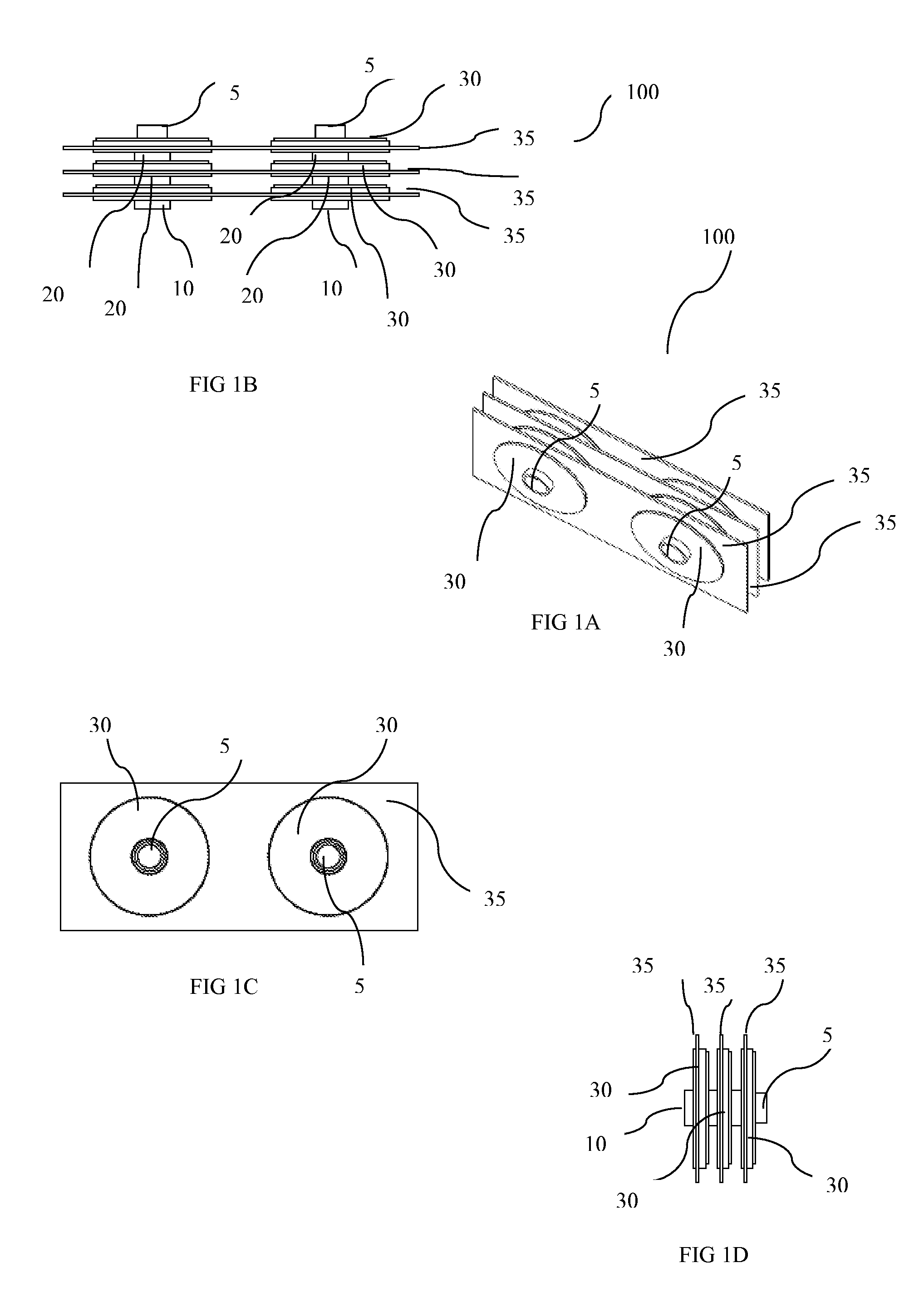
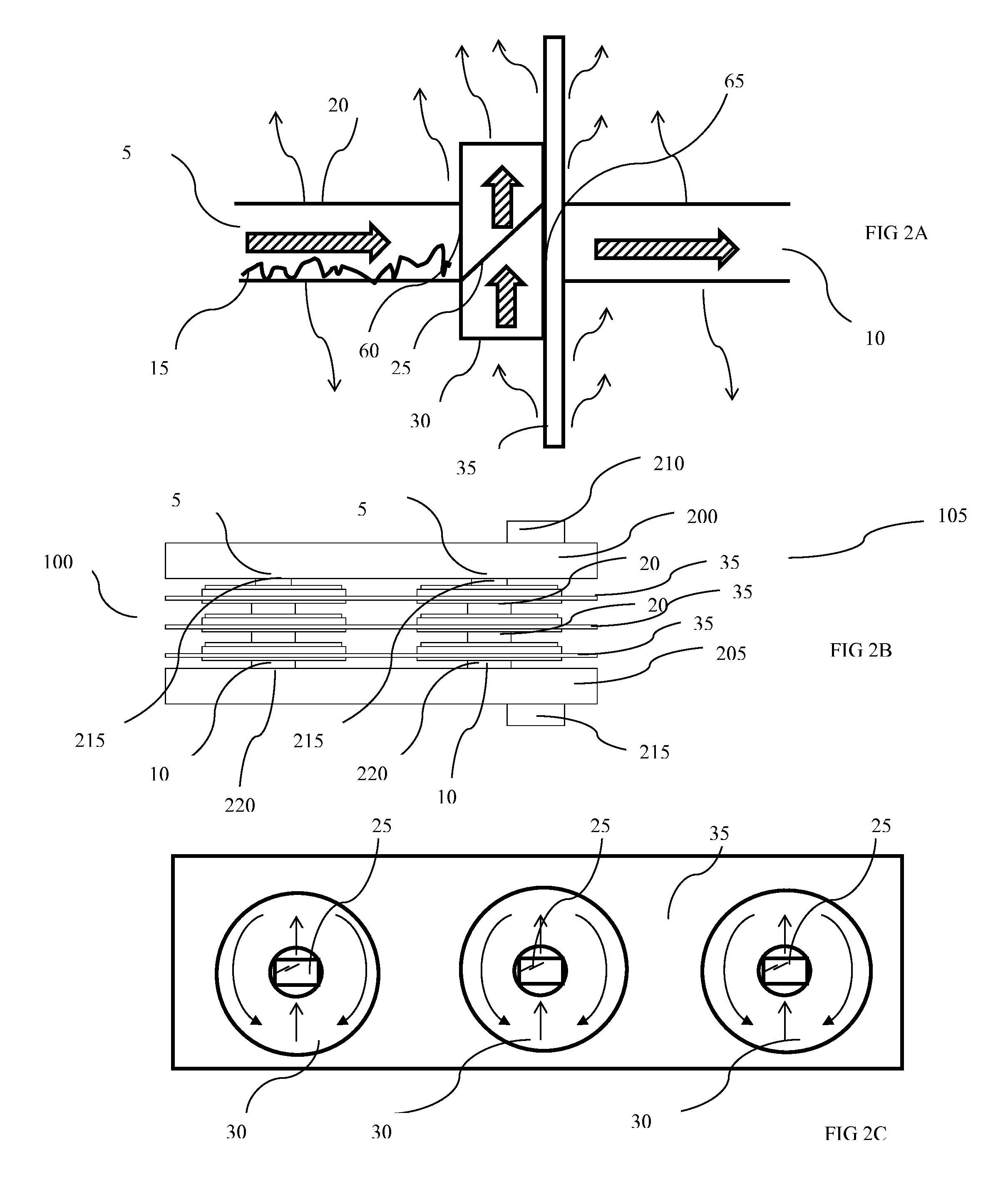
[0056]Referring to the drawings and in particular FIG. 1B and FIG. 2B, an embodiment of a heat exchanger 105 is shown. The heat exchanger 105 includes a pair of manifolds 200 and 205. Plurality of tube 20, chamber 30, and plate member 35 extend in spaced relation between a pair of manifolds 200 and 205, comprising a core 100 of the heat exchanger 105. One free end of tubes 20 coupled to manifold 200, and the other free end of tubes 20 coupled to manifold 205. Heat exchange medium 15 flows from the outlet 215 of the manifold 200 into the inlet 5 of the tube 20. The heat exchange medium 15 passes through the outlet 10 of the tube 20 into the inlet 60 of the chamber 30. The chamber 30 is coupled to a plate member 35. The heat exchange medium 15 then flow out outlet 65 of the chamber 30. The process of going from a tube 20 to a chamber 30 may repeat several times until the heat exchange medium 15 is received by another manifold 205. There may also be several rows of the tube 20, chamber...


PUM

PropertyMeasurementUnit
Dispersion potentialaaaaaaaaaa
Flow rateaaaaaaaaaa
Diameteraaaaaaaaaa

Abstract

A heat exchange unit having a plurality of chamber assembly coupled to a plate member, said chamber assembly including an inlet flow tube, an outlet flow tube, and a plurality of walls defining a chamber interior. Disposed within the chamber interior is a medium-directing member, having an inclined surface, diverting the heat exchange medium from the initial flow direction so that it disperses within the chamber interior, in to at least two distinct flow patterns. The heat exchange medium exits the chamber, via the outlet, in the initial line of flow. The chambers are interconnected by tubes to form assemblies. A plurality of plate member having plurality of chamber assembly is arranged on a spaced relation between manifolds to complete the medium flow.

Description

BACKGROUND OF THE INVENTION[0001]1. Field of the Invention[0002]The present invention relates generally to heat exchangers and, more specifically, to a heat exchanger having plurality of disk assemblies coupled to a plate member, each disk assemblies having a tube and a chamber apparatus, said chamber apparatus having a medium directing member within for transporting heat exchange medium.[0003]2. Discussion of the Related Art[0004]Heat exchangers are commonly utilized in systems where it is desired for heat to be removed. Typical basic heat exchangers are made of pipes, which channel heat exchanging medium. Headers or manifolds are attached to each end of the pipes. These headers and manifolds act as receptacles for the heat exchanging medium. The efficiency of the pipe heat exchangers is limited by the amount of surface area available for the transfer of heat. In a tube and chamber heat exchanger, plurality of tube and chamber extend in spaced relation between a pair of header or m...

Claims


Application Information

Patent Timeline
IPC IPC(8): F28F1/00B21D53/02
CPCB21D53/04F28F2210/00F28F13/08Y10T29/4935F28F1/22F28F1/24F28F1/30F28D1/05341
Inventor NITTA, MINORUNITTA, TAKEYOSHI
Owner MIKUTAY CORP
Why Eureka
Try Eureka