Cutting tooth with dual cutting edges for a brush cutting head

a cutting tooth and cutting head technology, applied in the field of brush cutting heads, can solve the problems of time-consuming, certain problems, and the design of the cutting tooth for this brush cutting head tends to suffer from certain disadvantages, and can not meet the needs of the user, and achieve the effect of improving the service life and reducing the cost of the produ

Inactive Publication Date: 2013-04-25
GYRO TRAC
View PDF1 Cites 29 Cited by
  • Summary
  • Abstract
  • Description
  • Claims
  • Application Information

AI Technical Summary

Benefits of technology

[0014]In an additional feature, the cutting tooth further includes means for preventing rotation of the cutting tooth relative to the mounting block. The rotation preventing means includes a pair of spaced apart, raised abutment members projecting from the trailing face of the base portion and extending longitudinally therealong. The spacing between the abutment members being sized large enough to accommodate a portion of the mounting block therein.

Problems solved by technology

However, the design of the cutting tooth for this brush cutting head tends to suffer from certain disadvantages.
Manufacture of the guide members projecting from the base portions of the cutting tooth must be precise and can be time consuming.
Moreover, certain problems have been encountered when replacing old, broken or worn cutting teeth on the brush cutting head.
In some cases, it has been found that the guide members projecting from the base portions of replacement cutting teeth do not always line up with the fittings on the mounting block into which they are to be received.
As a result of this misalignment, some cutting teeth could not be properly secured to the mounting blocks, thereby causing delay, excessive warranty claims and requiring operators to carry on hand a greater number of replacement cutting teeth than would ordinarily be required.

Method used


Image

  • Cutting tooth with dual cutting edges for a brush cutting head
  • Cutting tooth with dual cutting edges for a brush cutting head
  • Cutting tooth with dual cutting edges for a brush cutting head

Examples


Embodiment Construction

[0040]The description which follows, and the embodiments described therein are provided by way of illustration of an example, or examples of particular embodiments of principles and aspects of the present invention. These examples are provided for the purposes of explanation and not of limitation, of those principles of the invention. In the description that follows, like parts are marked throughout the specification and the drawings with the same respective reference numerals.

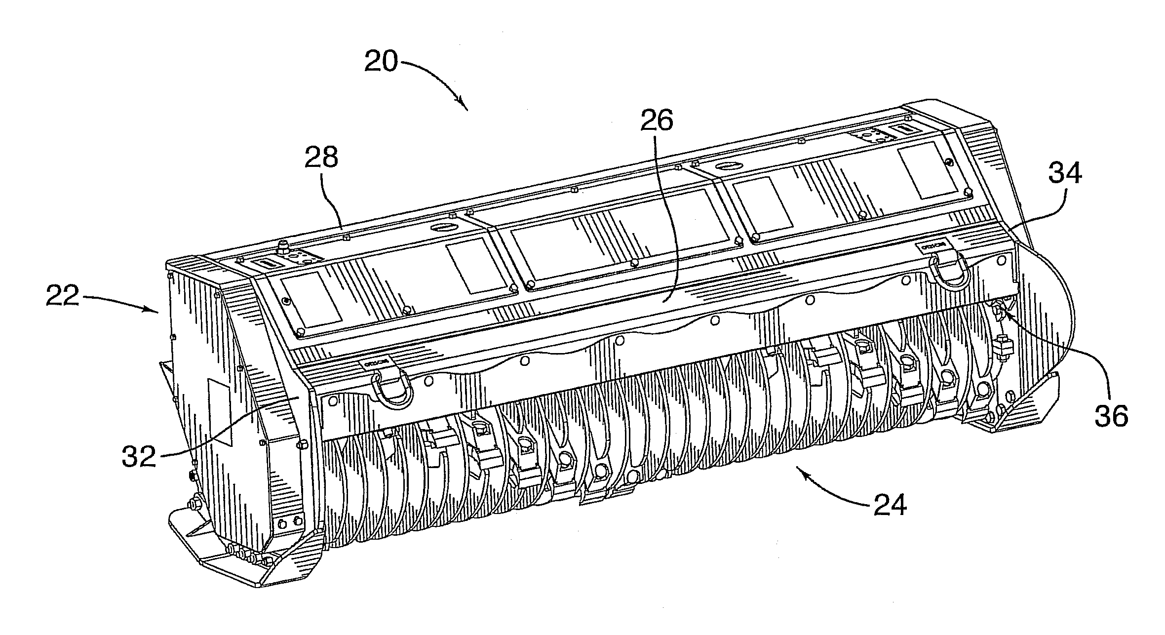
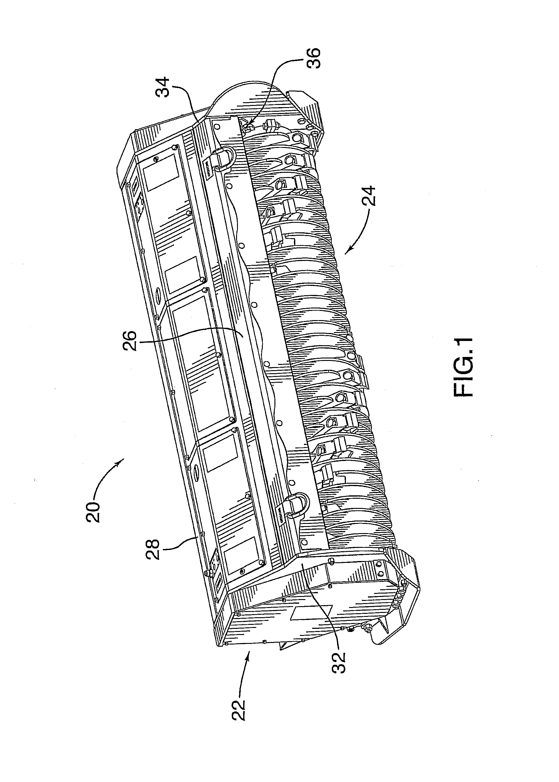
[0041]Referring to FIG. 1, there is shown a brush cutter generally designated with reference numeral 20. Brush cutter 20 may be of the type attached to the front of a vehicle, such as a loader, skid steer, or the like. Brush cutter 20 includes an open-bottom housing 22 and a brush cutting head 24 rotatably mounted within the housing 22. The housing 22 is defined generally by a front cover panel 26, a rear cover panel 28 and a pair of side panels 32 and 34. The cover panels 26 and 28 extend longitudinally betwe...


PUM


Abstract

The present invention relates to a cutting tooth for attachment to a mounting block. The cutting tooth includes a longitudinal body provided with leading and trailing faces, and opposed, first and second cutting portions. The leading face has a projection disposed thereon to reinforce the longitudinal body. The trailing face has defined therein at least one threaded, blind bore. The at least one blind bore extends substantially into the projection but stops short of a leading projection face. It is configured to receive therein a threaded bolt for securing the cutting tooth to the mounting block. The first cutting portion terminates in a first cutting edge having an angle of attack of between 20 and 75 degrees. The second cutting portion terminates in a second cutting edge having an angle of attack between 20 and 75 degrees.

Description

FIELD OF THE INVENTION[0001]The present invention relates generally to brush cutting heads, and more specifically, to a cutting tooth with dual cutting edges for a brush cutting head.BACKGROUND OF THE INVENTION[0002]Extensive felling and mulching operations are often performed with a heavy-duty brush cutter mounted to the front of a work vehicle. A typical brush cutter includes a brush cutting head provided with an elongate support body that carries about its outer surface a plurality of teeth adapted to cut trees, brush or the like. The cutting teeth are typically fixed to the outer surface of the drum via mounting blocks.[0003]An example of one such brush cutting head is described in United States Patent Publication No. 2010 / 0044487. This published patent application discloses a brush cutter that has a cylindrical support base and a plurality of mounting blocks fastened to the outer surface of the base. The bottom surface of each mounting block is concavely curved to match the rad...

Claims


Application Information

Patent Timeline
Patent Type & Authority Applications(United States)
IPC IPC(8): B27L11/00B02C18/18
CPCB02C18/18B02C18/145
Inventor GAUDREAULT, DANIEL
Owner GYRO TRAC
Why Eureka
Try Eureka