Check patentability & draft patents in minutes with Patsnap Eureka AI!

System and method for gradient amplifier control

a technology of gradient amplifier and control method, applied in the direction of dc-ac conversion, reradiation, instruments, etc., can solve the problems of inability to achieve desired output voltage through the use of conventional control techniques, and difficulties in the design of magnetic components and filters

Active Publication Date: 2013-04-25
GENERAL ELECTRIC CO
View PDF10 Cites 48 Cited by
  • Summary
  • Abstract
  • Description
  • Claims
  • Application Information

AI Technical Summary

Benefits of technology

This patent describes a method for operating a gradient amplifier to control the gradient coil in a magnetic resonance imaging (MRI) system. The method involves receiving feedback signals representing the input and output voltage, and generating a compensation signal based on these signals to achieve the desired DC voltage at the gradient amplifier. A regulator signal is then generated based on the output voltage feedback signal and the reference output voltage signal to control the inverter of the gradient amplifier. This method ensures accurate and stable control of the gradient coil, improving the quality of MRI images.

Problems solved by technology

However, varying the frequency of the switching signals may cause difficulties in design of magnetic components and filters in association with the series resonant converter.
Further, when input power or output load varies, desired output voltage cannot be achieved through the use of conventional control techniques.

Method used


Image

  • System and method for gradient amplifier control
  • System and method for gradient amplifier control
  • System and method for gradient amplifier control

Examples


Embodiment Construction

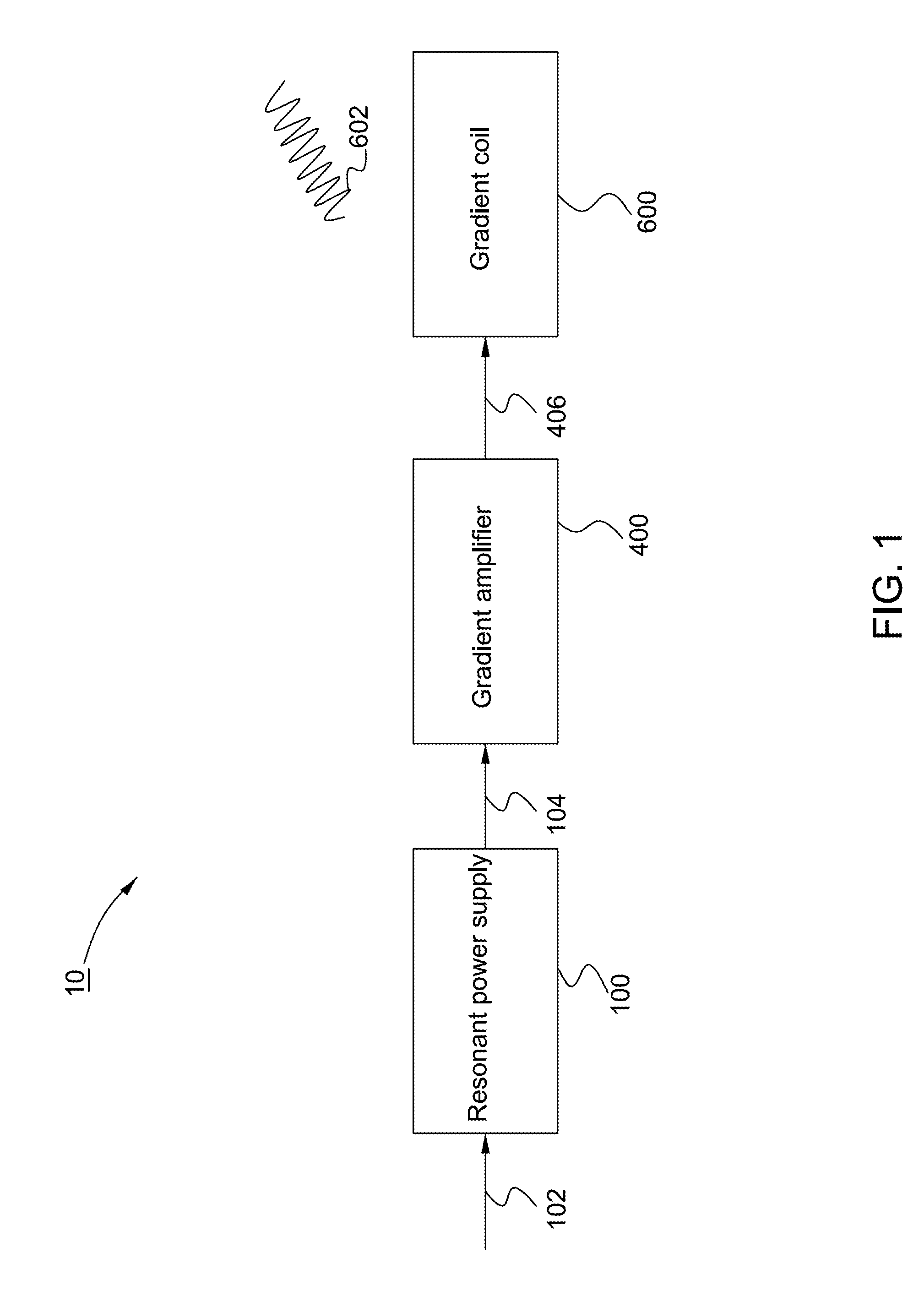
[0018]Exemplary embodiments disclosed herein relate to power supplies for supplying regulated power to a load. More specifically, a series resonant converter type power supply may be incorporated in a magnetic resonance imaging (MRI) system for supplying power to a gradient amplifier so as to enable the gradient amplifier to drive a gradient coil to generate gradient field to facilitate image acquisition. In particular, the power converted from the series resonant converter is regulated using a fixed frequency control algorithm. As used herein, “fixed frequency control algorithm” refers to the switching frequency of the switching devices used in the series resonant converter that is maintained at a constant value even when the input voltage to be regulated has fluctuations and the regulated voltage is experiencing transient conditions. In one implementation, the control is achieved by adjusting a phase delay between the switching signals for driving the switching devices in the seri...


PUM


Abstract

A gradient amplifier for driving a gradient coil is disclosed. The gradient amplifier includes a direct current (DC) bus for receiving DC voltage generated from a series resonant converter, an inverter coupled to the DC bus configured to receive the DC voltage at the DC bus and convert the DC voltage to generate an output voltage to be applied to the gradient coil, and an inverter controller coupled to the inverter. The inverter controller is configured to generate control signals to control operation of the inverter based at least on a DC voltage feedback signal measured at the DC bus, an output voltage feedback signal measured at the output of the inverter, and a reference output voltage signal indicative of a desired voltage to be achieved at the output of the inverter.

Description

BACKGROUND OF THE INVENTION[0001]Embodiments of the present invention relate to systems and methods for power supply control.[0002]Series resonant converters are one of the switching type power converters that have been widely used in a variety of industrial applications such as communication, medical, welding and so on. Typically, the series resonant converter can be operated to convert unregulated power received from a power source to regulated power which is applied to a load. The series resonant converter utilizes a number of switching devices arranged with half-bridge or full-bridge configurations that can be gated on or off to perform the power regulation. Conventionally, a frequency control is employed to control operation of the series resonant converter. That is, the frequency of the switching signals is varied with respect to the resonant frequency of a resonant tank circuit of the series resonant converter to achieve the desired output voltage from the series resonant con...

Claims


Application Information

Patent Timeline
Patent Type & Authority Applications(United States)
IPC IPC(8): G01R1/30H02M7/44G01R33/341
CPCY02B70/1433H02M3/3376G01R33/3852Y02B70/10
Inventor XU, FEIMA, TAOLU, XIWU, XINHUISHI, YIMENGZHU, PENGCHENGMORRIS, GARRON KOCHSABATE, JUAN ANTONIOSLOTNICK, JEFFREY NEAL
Owner GENERAL ELECTRIC CO
Features
  • R&D
  • Intellectual Property
  • Life Sciences
  • Materials
  • Tech Scout
  • Unparalleled Data Quality
  • Higher Quality Content
  • 60% Fewer Hallucinations
Learn More