Detecting apparatus and detecting method thereof
a detection apparatus and optical field technology, applied in the field of detecting apparatus and detecting method, can solve the problem of very expansive cost, and achieve the effect of reducing cost and fast and convenient detection
- Summary
- Abstract
- Description
- Claims
- Application Information
AI Technical Summary
Benefits of technology
Problems solved by technology
Method used
Image
Examples
first embodiment
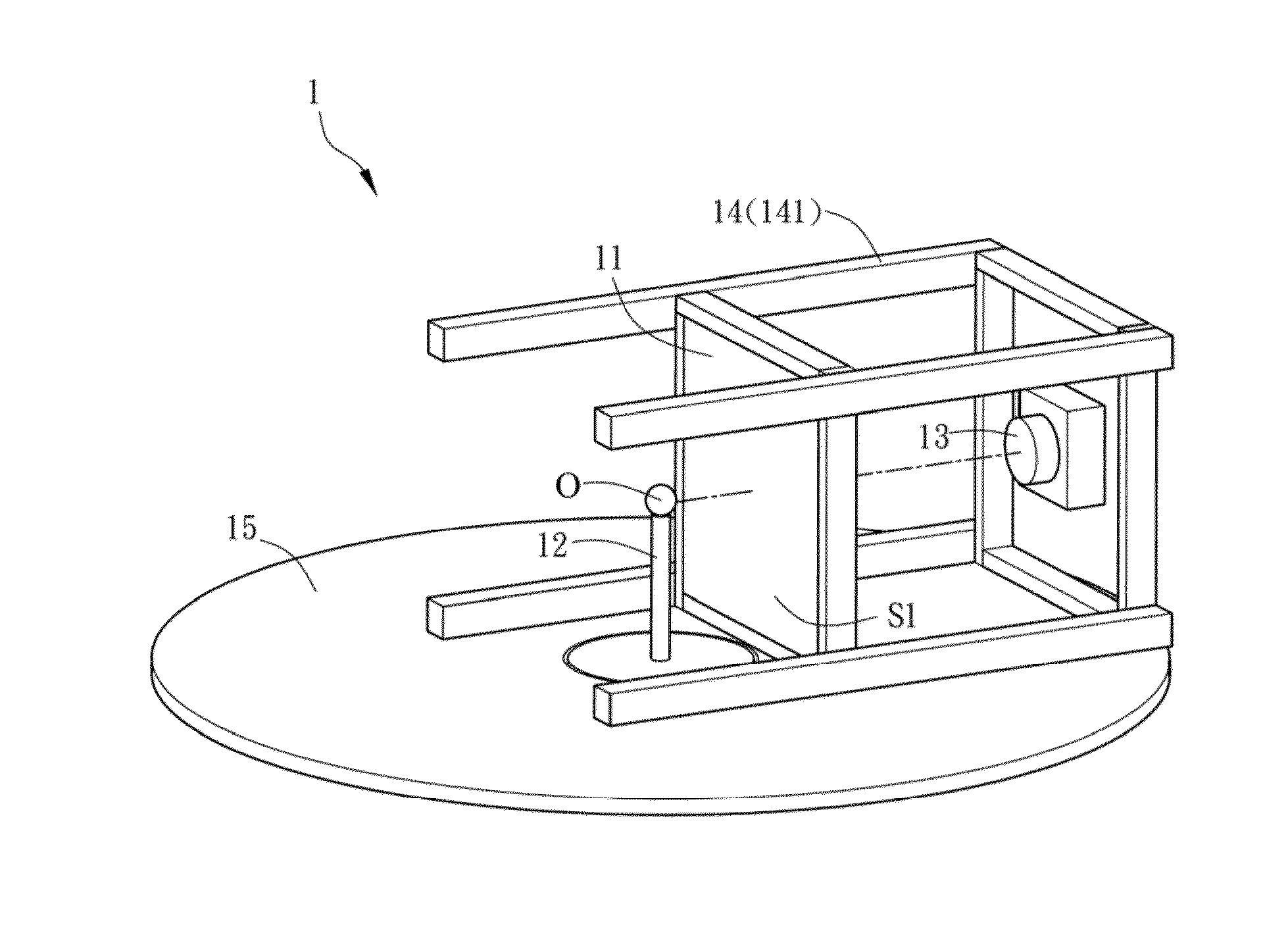
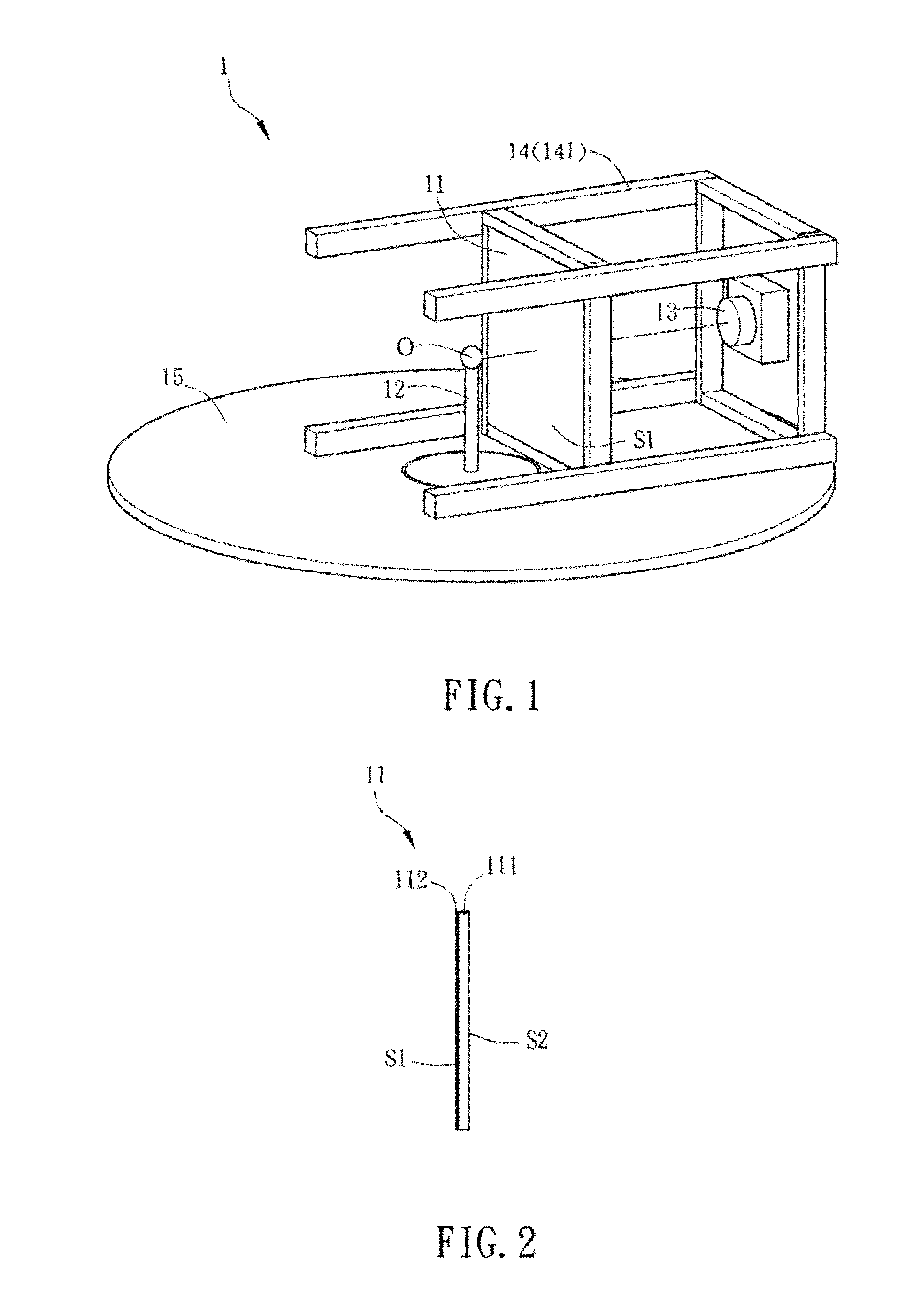
[0060]FIG. 1 is a schematic diagram of a detecting apparatus 1 according to the invention. With reference to FIG. 1, a detecting apparatus 1 of the invention is used for detecting an object and includes at least a screen 11, a carrier 12 for carrying the object, at least a detecting unit 13, and at least a holding unit 14. In this embodiment, the detecting apparatus 1 includes a screen 11, a detecting unit 13, and a holding unit 14. To be noted, the object to be detected is, for example, an optical film or a light source, such as LED, OLED, CCFL or HCFL. Besides, the object can be a light emitting element, a light source module, or an illumination device. Otherwise, the object to be detected can be an optical film such as a diffusion sheet (plate), a brightness enhancement film (BEF), a prism, or any other optical components. In this embodiment, as shown in FIG. 1, the object to be detected is a LED device O, and the carrier 12 carries the LED device O and has the driving circuit (n...
second embodiment
[0102]FIGS. 9A and 9B are schematic diagrams of a detecting apparatus 2 according to the invention.
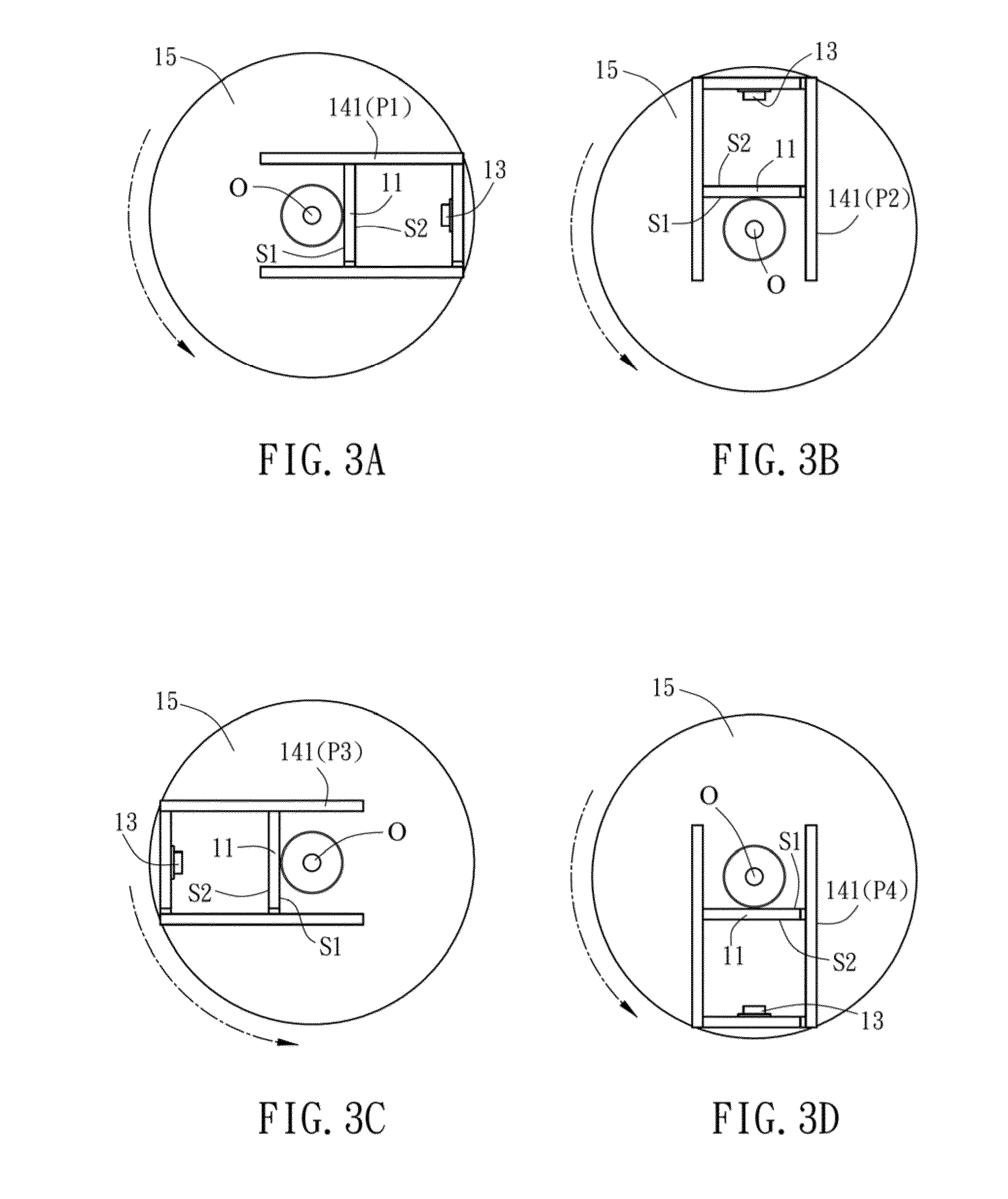
[0103]Different from the detecting apparatus 1a of the first embodiment, the holding unit 24 of the second embodiment includes a rotating bracket 242, and the screen 21 and the detecting unit 23 are fastened on the rotating bracket 242 for fixing the relative distance between the screen 21 and the detecting unit 23. By rotating the rotating bracket 242, the screen 21 and the detecting unit 23 can be moved with relative to the unmoved LED device O, so that the detecting unit 23 can capture different images of the second surface S2 of the screen 21 at different positions P1 and P5 as shown in FIGS. 3A to 3D.
[0104]In addition, the detecting apparatus 2 may further include a shell 26, which has a sector-like shape. The rotating bracket 242 is pivotally disposed on the shell 26, and the screen 21, the rotating bracket 242, the detecting unit 23 and the LED device O are all positioned inside...
third embodiment
[0106]FIG. 10 is a schematic diagram of a detecting apparatus 3 according to the invention.
[0107]Different from the detecting apparatus 1a of the first embodiment, the detecting unit 33 of the detecting apparatus 3 further includes a galvo mirror assembly 331 and a detecting device 332. The galvo mirror assembly 331 scans the image of every point of the second surface S2 of the screen 31 in sequence. In this case, the galvo mirror assembly 331 includes two optical galvo mirrors, and the detecting device 332 is a spectrometer for example. The two optical galvo mirrors are rotated relatively so as to scan the images of the second surface (not shown) of the screen 31 with different coordinates in sequence. In addition, the LED device O emits light to the screen 31, and the spectrometer receives the intensity of the light projected on different coordinates of the second surface. Moreover, since the LED device O is disposed on a rotating unit 35, it is possible to detect the light intens...
PUM
 Abstract
Description
Claims
Application Information
 - R&D
- Intellectual Property
- Life Sciences
- Materials
- Tech Scout
- Unparalleled Data Quality
- Higher Quality Content
- 60% Fewer Hallucinations
Browse by: Latest US Patents, China's latest patents, Technical Efficacy Thesaurus, Application Domain, Technology Topic, Popular Technical Reports.
© 2025 PatSnap. All rights reserved.Legal|Privacy policy|Modern Slavery Act Transparency Statement|Sitemap|About US| Contact US: help@patsnap.com


