Mask for EUV lithography, EUV lithography system and method for optimising the imaging of a mask

a mask and lithography technology, applied in the field of masks for euv lithography, euv lithography system and optimising the imaging of masks, can solve the problems of inability to have telecentric illumination of the mask in non-, inability to optimise two contributions to the telecentricity error separately, and inability to achieve telecentric illumination in non-, so as to improve image contrast and/or apodising during imaging, optimise the optical design of the mask

Active Publication Date: 2013-04-25
CARL ZEISS SMT GMBH
View PDF10 Cites 45 Cited by
  • Summary
  • Abstract
  • Description
  • Claims
  • Application Information

AI Technical Summary

Benefits of technology

[0050]Another aspect of the invention relates to a method for optimising the imaging of a mask in an EUV lithography system, the mask comprising: a substrate, a multi-layer coating applied to the substrate and a mask structure which is applied to the multi-layer coating and which has an absorber material, the optical design of the multi-layer coating in dependence of the mask structure and / or the optical design of the mask structure being selected in order to optimise the imaging in such a manner that at least one characteristic value of the EUV lithography system relevant to the imaging of the mask is improved, in particular maximised or minimised. For example, the telecentricity error, the image contrast and / or the apodising during imaging can be improved or optimised by adapting the optical design of the mask. For optimising the optical design of the multi-layer coating, in particular the thicknesses of the individual layers may be adapted in dependence of position. In order to optimise the optical design of the mask structure, the thickness of the mask structure and / or the lateral profile of the absorber layer or the absorber structures can be adapted in a suitable manner.
[0051]When a mask is provided for EUV lithography, it is generally advantageous also to carry out adaptation of the type and / or thickness of the absorber material in dependence of the numerical aperture or the chief ray angle CRA of the EUV lithography system, in which the mask is operated. It has been found that suitable absorber materials and optionally also the layer thicknesses are dependent on the selected numerical aperture, it not being advantageous for each aperture range if the thickness of the absorber layer is as small as possible and the absorption of the absorber material used is as large as possible. Instead, the layer thickness and the type of the absorber material must be selected carefully in order to achieve an optimised imaging quality.
[0052]It is also possible to apply, in place of a mask structure which has a single absorber layer, two or more absorber layers on top of each other which may also comprise different materials. As set out above, in this instance the absorber layers may have, for example, a different lateral extent so that the mask structures have a stair-like profile or a profile with oblique edges in place of a rectangular profile. Such a lateral profile can be adjusted by a suitable etching process. Consequently, corrections may be carried out in EUV masks by suitable adaptation of the lateral profile of the absorber layer and, for example, serve to correct the shadowing or to reduce the telecentricity error.
[0053]It will be appreciated that the multi-layer coating can also be modified in a suitable manner for the operation with a high numerical aperture because the angular range at which the mask is used also increases with the numerical aperture so that the multi-layer coating must act reflectively for a wide angular range. In this instance, both the adaptation of the multi-layer coating and the absorber layer can in particular be carried out in such a manner that optimum imaging is possible taking into consideration the illumination distribution and the transmission of the projection objective (Jones pupil) and other parameters relevant to the imaging. In this instance, in particular the illumination distribution (for example, a setting) in the object plane can also be adapted to the mask structure used (so-called source / mask optimisation) in addition to adapting the optical design of the mask.

Problems solved by technology

Therefore, it is not possible to have telecentric illumination of the mask in non-obscured systems because otherwise the illumination system and the objective lens would be in the way.
In addition to the imaging errors which are produced owing to the shadowing or the rigorous effects of the mask structure and which become perceptible in particular in the form of a telecentricity error, the fact that the multi-layer coating has a reflectivity which varies over the incidence angle range of the radiation which strikes the mask also results in a variation of apodisation in the objective pupil which also results in a telecentricity error during imaging.
However, those two contributions to the telecentricity error cannot be optimised separately from each other owing to the non-linearity of the rigorous effects to be considered.

Method used


Image

  • Mask for EUV lithography, EUV lithography system and method for optimising the imaging of a mask
  • Mask for EUV lithography, EUV lithography system and method for optimising the imaging of a mask
  • Mask for EUV lithography, EUV lithography system and method for optimising the imaging of a mask

Examples


Embodiment Construction

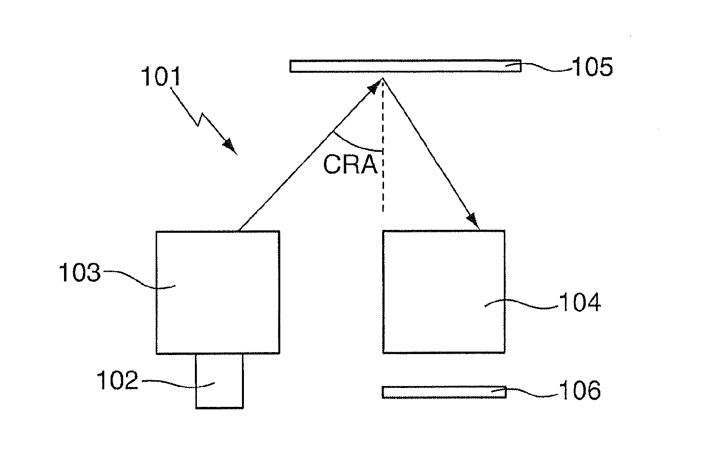
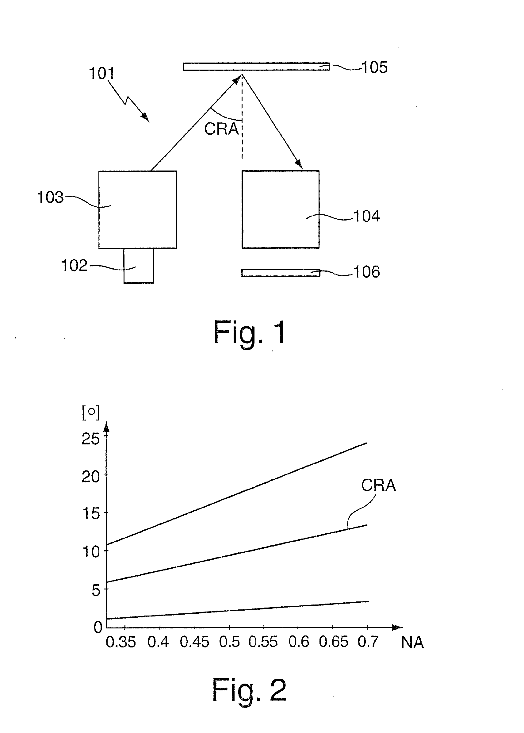
[0068]FIG. 1 illustrates an EUV lithography system 101 which has a beam shaping system 102, an illumination system 103 and a projection system 104 which are each accommodated in separate vacuum housings and which are arranged successively in a beam path which begins from an EUV light source (not illustrated) of the beam shaping system 102. For example, a plasma source or a synchrotron can be used as the EUV light source. The radiation being discharged from the EUV light source in the wavelength range between approximately 5 nm and approximately 20 nm is first bundled in a collimator (not illustrated); the desired operating wavelength, which is 13.5 nm in the present embodiment, is filtered out by the angle of incidence being varied by a downstream monochromator (not illustrated).

[0069]The radiation which is processed in the beam shaping system 102 with regard to wavelength and spatial distribution is introduced into the illumination system 103 which has optical elements (not illustr...


PUM

PropertyMeasurementUnit
thicknessaaaaaaaaaa
flank angleaaaaaaaaaa

Abstract

A mask (105) for EUV lithography includes a substrate (107), a multi-layer coating (108) applied to the substrate (107) and a mask structure (109) which is applied to the multi-layer coating (108) and which has an absorber material, the mask structure (109) having a maximum thickness of less than 100 nm, preferably not exceeding a maximum thickness of 30 nm, particularly preferably 20 nm, in particular 10 nm. Also disclosed is an EUV lithography system having such a mask (105) and a method for optimising the imaging of such a mask (105).

Description

REFERENCE TO RELATED APPLICATIONS[0001]This is a Continuation of International Application PCT / EP2011 / 059669, with an international filing date of Jun. 10, 2011, which was published under PCT Article 21(2) in English, and which claims the priority of U.S. Provisional Application No. 61 / 354,925, filed Jun. 15, 2010. The disclosures of both these parent applications are incorporated into the present Continuation in their entireties by reference.FIELD OF AND BACKGROUND OF THE INVENTION[0002]The invention relates to a mask for EUV lithography, an EUV lithography system having such a mask and a method for optimising the imaging of a mask in an EUV lithography system.[0003]Projection exposure systems for microlithography, referred to briefly as lithography systems below, generally comprise a light source, an illumination system which processes the light beams emitted by the light source to form illumination light, an object to be projected which is generally referred to as a reticle or ma...

Claims


Application Information

Patent Timeline
Patent Type & Authority Applications(United States)
IPC IPC(8): G03F7/20G03F1/22G03F1/24
CPCB82Y10/00B82Y40/00G03F7/70141G03F1/22G03F1/24G03F7/20G03F7/26H01L21/027
Inventor RUOFF, JOHANNESKRAEHMER, DANIEL
Owner CARL ZEISS SMT GMBH
Why Eureka
Try Eureka